This is an article giving details about the mathematics behind Cubic, Bezier and B-Spline Curves and Surfaces, along with code which runs in the Browser, using the Three.js JavaScript library. "Hello 3D".
1. Introduction
You can work on the application at https://amarnaths0005.github.io/3DCurvesSurfaces/#two[^].
You can also download the code at Github site
.
In Geometric Design, there are several types of curves and surfaces - both 2D and 3D. Among them, in introductory courses on Geometric Modelling, three types are generally taught - Cubic, Bezier and B-Spline Curves and Surfaces. It is the objective of this article to demonstrate and explain a program to draw these 3D curves and surfaces in the browser, using a 3D JavaScript library for WebGL, named Three.js.
This application is named CurSur, which is a short form for Curves and Surfaces.
In this article, I demonstrate how to draw a line and a surface in 3D, in the browser, using Three.js, and also to modify the geometric parameters like control points and tangents (derivatives) of these curves and surfaces. The main requirements of the code given here are:
- Should display these six types of 3D curves and surfaces on the screen - Parametric Cubic Curve, Coons Bicubic Surface, Bezier Curve, Bezier Surface, B-Spline (in fact, NURBS) Curve, and NURBS Surface.
- Should enable the user to modify the x, y, z coordinates of control points, and/or the derivatives with respect to x, y, z (tangents) of the curve or surface, and see how the curve or surface gets modified dynamically on the screen.
- Should enable the user to view the surface in wireframe mode as well.
- Should display the bounding box of the curve or surface, which has a dimension of 2 units, centered at the origin.
- Should enable the user to modify the camera angle, such that the camera gets rotated about the vertical axis, around the scene being viewed.
- Should enable the user to modify the parameters values - u in case of a curve, and u, w in case of a surface, and see that corresponding point move on the curve and surface as these u, w values are varied.
- Should display some standard curves and surfaces at the click of a button.
- Should use the Three.js library to display the 3D curve or surface on the screen.
- Should use Vanilla JS and not any framework.
- There should be no textbox type of user input, and all user interactions should be through sliders, checkboxes, comboboxes and buttons only.
- Added Feb 2023: Should enable the user to input an image and show this image as a texture on the surface rendered. And update to Revision 149 of Three.js.
2. Introduction to Parametric Curves and Surfaces
As students, we learn in High School and Intermediate College that there are Cartesian and Polar forms of representation of lines, like straight lines, circular arcs, conics, and so on. However, for purposes of Geometric Design, the Cartesian and Polar forms are not generally preferred for many reasons, two of which are (i) Representation of vertical or near vertical lines is not easy in Cartesian form, since the slope (derivative) tends to blow up, and (ii) It is not easy to represent a general shape in these Cartesian and Polar forms. As a result, the preferred form is parametric.
In the Parametric Form, a 3D curve is represented as:
x = x(u)
y = y(u)
z = z(u)
where x, y, z are the 3D coordinates of any point on that curve, and u is a parameter, usually within the range 0 ≤ u ≤ 1. Where x(u), y(u), z(u) are three functions of the parameter u. With this representation, it becomes easy to represent any shape of line, and it does not suffer from the disadvantages like infinite derivatives as in the Cartesian representation. In particular, we see three such functions for these x(u), y(u), z(u) and these define the three types of curves in this article - the Parametric Cubic, Bezier and B-Spline.
In a similar way, it is also possible to represent surfaces, using the equation:
x = x(u,w)
y = y(u,w)
z = z(u,w)
where, as usual, x, y, z are the 3D coordinates of a point on the surface, and u, w are two parameters in mutually perpendicular directions in the parametric space, and usually within the range 0 ≤ u ≤ 1, 0 ≤ w ≤ 1. Here again, the three functions x(u,w), y(u,w), z(u,w) take three different forms for the Bicubic, Bezier and B-Spline representations.
3. Drawing in Three.js
A curve is drawn as a number of straight-line segments, joined end on end to give the appearance of a smooth curve, and therefore, the most fundamental thing to do is to draw a 3D straight line in the browser.
Since the coming of WebGL, there have been JavaScript 3D libraries which abstract the inner details of the actual WebGL library, and two popular such JavaScript libraries are Three.js and Babylon.js. In this article, I have used the Three.js library, and will show code extracts about how to draw lines and surfaces on the screen.
The three most important entities which are required for drawing a 3D object in Three.js are a Scene, Camera and Renderer. The code for this is given below:
scene = new THREE.Scene();
camera = new THREE.PerspectiveCamera(45, window.innerWidth / window.innerHeight, 0.1, 1000 );
renderer = new THREE.WebGLRenderer({ antialias: true });
3A. Drawing a Straight Line in Three.js
A straight line segment is determined by its two end points in space (x1, y1, z1) and (x2, y2, z2).
For drawing a straight line segment, there is a Geometry object in Three.js, called BufferGeometry. Earlier, there was a Geometry object, but this has been deprecated in Revision 125 of Three.js, and the BufferGeometry object is to be used in its place.
In addition, a material is to be specified. There are different materials for lines and surfaces.
Drawing a straight line segment is done using the following code:
const material = new THREE.LineBasicMaterial({ color: 0xff00ff });
const geometry = new THREE.BufferGeometry();
const vertices = [];
vertices.push(-0.75, -0.75, -0.75);
vertices.push(0.75, 0.75, 0.75);
geometry.setAttribute(
    "position",
    new THREE.Float32BufferAttribute(vertices, 3));
let line = new THREE.Line(geometry, material);
scene.add(line);
render();
In the above code, a straight line is drawn between the endpoints (-0.75, -0.75, -0.75) and (0.75,0.75,0.75), as shown by the magenta line in the figure below:

3B. Drawing a Simple Surface in Three.js
A surface is defined as a set of triangles. The basic geometric entity to draw is therefore a triangle. A triangle in 3D is specified by its three vertices (x1, y1, z1), (x2, y2, z2) and (x3, y3, z3). We cannot just draw the three straight lines defining the triangle, since that would show up as a wireframe figure.
If the scene contains only a set of line segments, then no additional light is needed to illuminate the scene. However, if there are surfaces or 3D objects (like cube, sphere, etc.) in the scene, then one or more lights have to be specified. There are different types of lights, and these are defined in the Three.js documentation. The code for adding a couple of lights to the scene is shown below:
scene.add(new THREE.HemisphereLight(0x606060, 0x404040));
let directionalLight = new THREE.DirectionalLight(0xffffff, 0.65);
scene.add(directionalLight);
To specify the triangle as a surface, we need to define the normal to the triangle. Now, there are two normals to a triangle, both pointing in opposite directions. If the material is specified as double sided, then both the sides of the triangle will be displayed, with the lights defined. However, if the surface is specified as single sided, then the side where light does not fall on, is not likely to be illuminated. The uv values are used to define a texture, mapping an image coordinate to a point on the surface.
The code for drawing a triangulated surface on the scene is shown below:
function computeCoonsBicubicSurface() {
setupFourPoints();
surfacePoints.length = 0;
let uVal, wVal;
for (let j = 0; j <= noDivisions; ++j) {
wVal = j * step;
for (let i = 0; i <= noDivisions; ++i) {
uVal = i * step;
let pt = computePointOnSurface(uVal, wVal);
surfacePoints.push(pt.xVal, pt.yVal, pt.zVal);
uvArray.push(1.0 - wVal);
uvArray.push(uVal);
}
}
renderCoonsBicubicSurface();
handleUWValue();
}
function renderCoonsBicubicSurface() {
scene.remove(surfaceMesh);
scene.remove(lineWire);
let material = new THREE.MeshStandardMaterial({
side: THREE.DoubleSide,
color: 0x00ffff,
emissive: 0x111111,
dithering: true,
flatShading: false,
roughness: 1,
metalness: 0.15,
skinning: true,
});
let materialLine = new THREE.LineBasicMaterial({
color: 0x00ffff,
});
let materialT = new THREE.MeshBasicMaterial({
map: textureImage,
side: THREE.DoubleSide,
});
let geometry = new THREE.BufferGeometry();
const indices = [];
indices.length = 0;
for (let i = 0; i < noDivisions; i++) {
for (let j = 0; j < noDivisions; j++) {
const a = i * (noDivisions + 1) + (j + 1);
const b = i * (noDivisions + 1) + j;
const c = (i + 1) * (noDivisions + 1) + j;
const d = (i + 1) * (noDivisions + 1) + (j + 1);
indices.push(a, b, d);
indices.push(b, c, d);
}
}
geometry.setAttribute(
"position",
new THREE.Float32BufferAttribute(surfacePoints, 3).onUpload(disposeArray)
);
const uvNumComponents = 2;
geometry.setAttribute(
"uv",
new THREE.BufferAttribute(
new Float32Array(uvArray),
uvNumComponents
).onUpload(disposeArray)
);
geometry.setIndex(indices);
geometry.computeVertexNormals();
if (document.getElementById("wireframe").checked === true) {
let surfaceWire = new THREE.WireframeGeometry(geometry);
lineWire = new THREE.LineSegments(surfaceWire, materialLine);
scene.add(lineWire);
} else {
if (textureCheck.checked === true) {
materialT.map = new THREE.CanvasTexture(canvasBig);
surfaceMesh = new THREE.Mesh(geometry, materialT);
} else {
surfaceMesh = new THREE.Mesh(geometry, material);
}
surfaceMesh.material.needsUpdate = true;
scene.add(surfaceMesh);
render();
}
where surfacePoints is an array of points defined above. A surface drawn with the above code is shown below. As the number of triangles increases, the surface starts giving a smooth appearance. Please look at the file script2.js for the complete code.
4. Parametric Cubic Curve in 3D
A Parametric Cubic Curve is defined by the following three equations:
x(u) = B0x + B1x u + B2x u2 + B3x u3
y(u) = B0y + B1y u + B2y u2 + B3y u3
z(u) = B0z + B1z u + B2z u2 + B3z u3
Here, the 12 constants B0x, B1x, B2x, B3x, B0y, B1y, B2y, B3y, B0z, B1z, B2z, B3z, are constants to be determined from the points on the curve.
There are two ways by which these constants can be determined:
- Four Point Form: If four points along the curve are known, then the coordinates of these four points specify twelve equations to determine the twelve constants.
- Hermite Form: If the coordinates of two end points are known, and the two end tangents (rather derivatives with respect to x, y, z at the end points) are known, then these also specify twelve equations to determine the twelve constants
These are the two methods presented in the application accompanying this article. Derivation of the equations corresponding to these two forms are given in the book Geometric Modeling by Mortenson, or in the book Mathematical Elements for Computer Graphics by Rogers and Adams. For the Hermite Form, the derivatives of the x, y, z equations with respect to the x, y, z coordinates, and these are also given in the books mentioned above.
4A. Four Point Form
For this Four Point Form, we need to specify the u values for the four points. For purposes of this code, we take these as 0, 1/3, 2/3 and 1. For these values of the parameter u, substituting them into the equations of the curve, the values of the constants Bij can be determined. As the values of the coordinates of any of the four points are varied using the scrollbars for the coordinate values, these constants Bij are calculated dynamically, the new coordinates of all points on the curve are computed, and the curve is refreshed on the screen. The code for this is:
function computePointFourPointForm(uVal) {
let u2, u3;
let coeff1, coeff2, coeff3, coeff4;
let xCurve, yCurve, zCurve;
u2 = uVal * uVal;
u3 = u2 * uVal;
coeff1 = -4.5 * u3 + 9 * u2 - 5.5 * uVal + 1;
coeff2 = 13.5 * u3 - 22.5 * u2 + 9 * uVal;
coeff3 = -13.5 * u3 + 18 * u2 - 4.5 * uVal;
coeff4 = 4.5 * u3 - 4.5 * u2 + uVal;
xCurve = p1x * coeff1 + p2x * coeff2 + p3x * coeff3 + p4x * coeff4;
yCurve = p1y * coeff1 + p2y * coeff2 + p3y * coeff3 + p4y * coeff4;
zCurve = p1z * coeff1 + p2z * coeff2 + p3z * coeff3 + p4z * coeff4;
return {
xVal: xCurve,
yVal: yCurve,
zVal: zCurve,
};
}
4 B. Hermite Form
For this form, the two end points and two sets of derivatives at these end points are specified, and these are used to compute the constants Bij. These are also from the formula given in Mortenson's book. The code for this is:
function computePointHermiteForm(uVal) {
let u2, u3;
let coeff1, coeff2, coeff3, coeff4;
let xCurve, yCurve, zCurve;
u2 = uVal * uVal;
u3 = u2 * uVal;
coeff1 = 2 * u3 - 3 * u2 + 1;
coeff2 = -2 * u3 + 3 * u2;
coeff3 = u3 - 2 * u2 + uVal;
coeff4 = u3 - u2;
xCurve = p1xh * coeff1 + p2xh * coeff2 + p1dxh * coeff3 + p2dxh * coeff4;
yCurve = p1yh * coeff1 + p2yh * coeff2 + p1dyh * coeff3 + p2dyh * coeff4;
zCurve = p1zh * coeff1 + p2zh * coeff2 + p1dzh * coeff3 + p2dzh * coeff4;
return {
xVal: xCurve,
yVal: yCurve,
zVal: zCurve,
};
}
When the scrollbars corresponding to the end coordinates and the derivatives are modified by the user using the scrollbars on the screen, the constants B ij are dynamically calculated and the entire curve is re-calculated.
4C. Code for the Parametric Cubic Curve
The curve is rendered as a set of straight line segments on the curve. The entire parametric range 0 ≤ u ≤ 1 is divided into a number of parts, and all the straight line segments are drawn in a loop. The code for this is, and is in the file script1.js. The corresponding HTML is in the file page1.html.
let curvePoints = [];
curvePoints.length = 0;
for (let i = 0; i < noUPoints; ++i) {
uVal = uStep * i;
let pt = computePointFourPointForm(uVal);
curvePoints.push(pt.xVal, pt.yVal, pt.zVal);
}
4D. Validation
For validation a set of standard values for the point coordinates / derivatives are used, and the shape of the resulting curve is seen. Also, the point on the curve, as obtained by varying the parameter u is seen on the screen, and used for validation.
- An interesting case to note here is that of a Nonlinear Straight Line. It is not generally true that for equal increments of parameter u, equal distances along the curve are traversed. This brings in the nonlinearity element into the Parametric Cubic Curve. This is a Nonlinear Straight Line. Even though the points all lie on the same straight line, different parameter increments cause different distances of traversal along that straight line.
- In the Hermite Form, for a straight line, it may so happen that the endpoint derivatives are in directions outside the straight line segment. In such a case, upon increasing the parameter u from 0 to 1, the point goes outside the straight line segment, and then it reverses its direction, and then goes towards the second end point. This is again a Nonlinear Straight line.
- Some such cases are given on the screen in the form of Buttons specifying Interesting Curves.
5. Bezier Curve in 3D
In the Parametric Cubic Curve shown above, especially in the Four Point Form, the curve passes through all the four points, which is a form of curve fitting. Bezier Curves were introduced by P Bezier, who defined an equation the curve in terms of control points. The Bezier Curve is defined by this equation
In our application, we have considered a Bezier Curve with 5 control points, so the highest degree of u in the polynomial is 4.
5A. Code for the Bezier Curve
As in the case of the Parametric Cubic Curve, the Bezier curve is also rendered as a set of straight line segments on the curve. The entire parametric range 0 ≤ u ≤ 1 is divided into a number of parts, and all the straight line segments are drawn in a loop. The code for this is in the file script3.js which corresponds to the HTML file page3.html:
u2 = uVal * uVal;
u3 = u2 * uVal;
u4 = u3 * uVal;
coeff1 = u4 - 4 * u3 + 6 * u2 - 4 * uVal + 1;
coeff2 = -4 * u4 + 12 * u3 - 12 * u2 + 4 * uVal;
coeff3 = 6 * u4 - 12 * u3 + 6 * u2;
coeff4 = -4 * u4 + 4 * u3;
coeff5 = u4;
xCurve = p1x * coeff1 + p2x * coeff2 + p3x * coeff3 + p4x * coeff4 + p5x * coeff5;
yCurve = p1y * coeff1 + p2y * coeff2 + p3y * coeff3 + p4y * coeff4 + p5y * coeff5;
zCurve = p1z * coeff1 + p2z * coeff2 + p3z * coeff3 + p4z * coeff4 + p5z * coeff5;
5B. Validation
There are these validation aspects for a Bezier Curve:
- The curve should pass through the end points, and not through the other control points in the general case.
- However, when all the control points are in a straight line, the curve should also be the straight line passing through these points.
- The tangents to the curve at the end points should be in line with the line joining that particular end point with its next control point. For example, at the beginning of the curve, the tangent to the curve should be in line with the straight line joining the first and second control points. Similarly at the end control point.
All these points are verified for the Bezier Curve, and a set of Interesting Bezier Curves are drawn, each having a button of its own on the screen.
6. NURBS Curve in 3D
NURBS stands for Non Uniform Rational B-Spline Curve. The necessity for such a curve arose because both Parametric Cubic and Bezier Curves do not permit local control of the curve. In other words, for Parametric Cubic and Bezier curves, modifying one control point modifies the entire curve, and this is not desirable in a number of applications. B-Spline curves, on the other hand, allow local control of the curve. Modifying the coordinates of a control point cause modification of the curve only in the vicinity of that control point, and the remainder of the curve is unaffected.
The general equation for a Rational B-Spline Curve is as follows:
The degree of a NURBS Curve does not depend on the number of Control Points. These two are independent entities in a NURBS Curve.
In our application, we initially define six control points, and allow the user to add control points (up to a total of 20 control points), and modify the coordinates (the x, y, z, h values) of each of these control points, and visualize the resulting NURBS Curve.
6A. Code for the Nurbs Curve
Since Three.js already has an open-source code for a NURBS Curve, we do not intend to re-invent the wheel. So, here, we have taken the relevant extracts of the NURBS Curve code from there, and have included it in a file called NurbsHelper.js.
In our code, to specify control points, we generate them as random numbers within the bounding box of dimension 2, centred at the origin.
Though, in reality, the NURBS Curve is the most complex of the three curves in our application, the code for that - script5.js is the simplest, and it just calls the relevant functions within the file NurbsHelper.js. The corresponding HTML file is page5.html.
6B. Validation
- As already mentioned above, a NURBS Curve allows local control, which means that by modifying the coordinates (x, y, z, h) one point, the curve gets modified only locally, and the other part of the curve remains unchanged. This is a property which can be easily verified visually.
- Another point to verify is that by modifying the value of the homogeneous coordinate h of a control point. This should pull the curve towards this control point. This is also verified visually.
- Yet another verification point is in modifying the degree of the curve. For a value of this degree equal to 1, the curve resembles the Control Polygon itself. As the degree of the curve is increased, the curve moves away from the control points (except at the endpoints), and for higher values of these degrees, the curve is farthest from its corresponding control points.
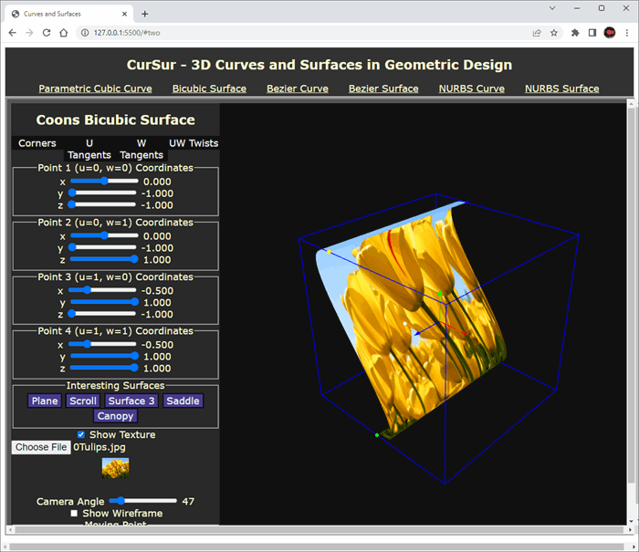
7. Coons Bicubic Surface
The two dimensional equivalent of a Parametric Cubic Curve is the Coons Bicubic Surface. The equations of such a surface are given below:
In parametric space, there are two parameters u and w which vary in the range [0, 1]. The following boundary conditions need to be defined for a Coons Bicubic Surface:
- Four end points of the rectangular patch.
- Tangent vectors with respect to parameter u at these end points. These are partial derivatives with respect to u.
- Tangent vectors with respect to parameter w at these end points. These are partial derivatives with respect to w.
- Twist vectors with respect to the parameters u, w at these end points. These are partial derivatives with respect to both u and w.
When any of the above are changed, the surface changes.
All of these are shown in following figure:
The boundaries of the patch are these four curves:
- Curve where u is increasing and w is 0.
- Curve where w is increasing and u is 0.
- Curve where u is increasing and w is 1.
- Curve where w is increasing and u is 1.
7A. Code for the Coons Bicubic Surface
The following JavaScript function computes a point on the surface, in file script2.js.
function computePointOnSurface(uVal, wVal) {
  let u2, u3, w2, w3;
  let f1u, f2u, f3u, f4u, f1w, f2w, f3w, f4w;
  let valueX, valueY, valueZ;
  let valx1, valx2, valx3, valx4;
  let valy1, valy2, valy3, valy4;
  let valz1, valz2, valz3, valz4;

  w2 = wVal * wVal;
  w3 = w2 * wVal;
  f1w = 2.0 * w3 - 3 * w2 + 1.0;
  f2w = -2.0 * w3 + 3.0 * w2;
  f3w = w3 - 2.0 * w2 + wVal;
  f4w = w3 - w2;
  u2 = uVal * uVal;
  u3 = u2 * uVal;
  f1u = 2.0 * u3 - 3 * u2 + 1.0;
  f2u = -2.0 * u3 + 3.0 * u2;
  f3u = u3 - 2.0 * u2 + uVal;
  f4u = u3 - u2;

  valx1 = f1u * (p1x * f1w + p2x * f2w + p1wx * f3w + p2wx * f4w);
  valx2 = f2u * (p3x * f1w + p4x * f2w + p3wx * f3w + p4wx * f4w);
  valx3 = f3u * (p1ux * f1w + p2ux * f2w + p1uwx * f3w + p2uwx * f4w);
  valx4 = f4u * (p3ux * f1w + p4ux * f2w + p3uwx * f3w + p4uwx * f4w);
  valueX = valx1 + valx2 + valx3 + valx4;

  valy1 = f1u * (p1y * f1w + p2y * f2w + p1wy * f3w + p2wy * f4w);
  valy2 = f2u * (p3y * f1w + p4y * f2w + p3wy * f3w + p4wy * f4w);
  valy3 = f3u * (p1uy * f1w + p2uy * f2w + p1uwy * f3w + p2uwy * f4w);
  valy4 = f4u * (p3uy * f1w + p4uy * f2w + p3uwy * f3w + p4uwy * f4w);
  valueY = valy1 + valy2 + valy3 + valy4;

  valz1 = f1u * (p1z * f1w + p2z * f2w + p1wz * f3w + p2wz * f4w);
  valz2 = f2u * (p3z * f1w + p4z * f2w + p3wz * f3w + p4wz * f4w);
  valz3 = f3u * (p1uz * f1w + p2uz * f2w + p1uwz * f3w + p2uwz * f4w);
  valz4 = f4u * (p3uz * f1w + p4uz * f2w + p3uwz * f3w + p4uwz * f4w);
  valueZ = valz1 + valz2 + valz3 + valz4;

  return {
    xVal: valueX,
    yVal: valueY,
    zVal: valueZ,
  };
}
7B. Validation
The following are the validation aspects:
- When the coordinates of a boundary point are varied using their sliders, then that corresponding boundary point should vary, in the direction specified x, y or z, and the surface should correspondingly change.
- The same should happen when the Tangent Vectors in u or v directions are changed using their sliders, though the change is not as tangibly perceived as when changing the coordinate value.
- Similarly, when the Twist vectors are changed, the surface should change.
- Some predefined surfaces are also presented which appear upon clicking of the buttons at the bottom of the left pane.
8. Bezier Surface
The two-dimensional (in parametric space) equivalent of a Bezier Curve is a Bezier Surface. The equations for such a surface are given below:
8A. Code for the Bezier Surface
The following JavaScript function computes a point on the Bezier Surface, in file script4.js. For purposes of this article, the code provided is for a 4 x 4 Bezier Surface, with a total of 16 Control points. The corresponding HTML file is page4.html.
function computeBezierSurfacePoint(uVal, wVal) {
let u2, u3, w2, w3;
u2 = uVal * uVal;
u3 = uVal * u2;
w2 = wVal * wVal;
w3 = wVal * w2;
let matC = new THREE.Matrix4();
matC.set(-1, 3, -3, 1, 3, -6, 3, 0, -3, 3, 0, 0, 1, 0, 0, 0);
let matPx = new THREE.Matrix4();
matPx.set(
p00x, p10x, p20x, p30x, p01x, p11x, p21x, p31x,
p02x, p12x, p22x, p32x, p03x, p13x, p23x, p33x
);
let matPy = new THREE.Matrix4();
matPy.set(
p00y, p10y, p20y, p30y, p01y, p11y, p21y, p31y,
p02y, p12y, p22y, p32y, p03y, p13y, p23y, p33y
);
let matPz = new THREE.Matrix4();
matPz.set(
p00z, p10z, p20z, p30z, p01z, p11z, p21z, p31z,
p02z, p12z, p22z, p32z, p03z, p13z, p23z, p33z
);
let mat1x = new THREE.Matrix4();
mat1x.multiplyMatrices(matC, matPx);
let mat1y = new THREE.Matrix4();
mat1y.multiplyMatrices(matC, matPy);
let mat1z = new THREE.Matrix4();
mat1z.multiplyMatrices(matC, matPz);
let mat2x = new THREE.Matrix4();
mat2x.multiplyMatrices(mat1x, matC);
let mat2y = new THREE.Matrix4();
mat2y.multiplyMatrices(mat1y, matC);
let mat2z = new THREE.Matrix4();
mat2z.multiplyMatrices(mat1z, matC);
let ex = mat2x.elements;
let w0x = ex[0] * w3 + ex[4] * w2 + ex[8] * wVal + ex[12];
let w1x = ex[1] * w3 + ex[5] * w2 + ex[9] * wVal + ex[13];
let w2x = ex[2] * w3 + ex[6] * w2 + ex[10] * wVal + ex[14];
let w3x = ex[3] * w3 + ex[7] * w2 + ex[11] * wVal + ex[15];
let ey = mat2y.elements;
let w0y = ey[0] * w3 + ey[4] * w2 + ey[8] * wVal + ey[12];
let w1y = ey[1] * w3 + ey[5] * w2 + ey[9] * wVal + ey[13];
let w2y = ey[2] * w3 + ey[6] * w2 + ey[10] * wVal + ey[14];
let w3y = ey[3] * w3 + ey[7] * w2 + ey[11] * wVal + ey[15];
let ez = mat2z.elements;
let w0z = ez[0] * w3 + ez[4] * w2 + ez[8] * wVal + ez[12];
let w1z = ez[1] * w3 + ez[5] * w2 + ez[9] * wVal + ez[13];
let w2z = ez[2] * w3 + ez[6] * w2 + ez[10] * wVal + ez[14];
let w3z = ez[3] * w3 + ez[7] * w2 + ez[11] * wVal + ez[15];
let qx = u3 * w0x + u2 * w1x + uVal * w2x + w3x;
let qy = u3 * w0y + u2 * w1y + uVal * w2y + w3y;
let qz = u3 * w0z + u2 * w1z + uVal * w2z + w3z;
return {
xVal: qx,
yVal: qy,
zVal: qz,
};
}
8B. Validation
- Here again, when any of the control points are changed (coordinates), the corresponding surface should also change. This is verified by looking at the surface rendered.
- A number of interesting surfaces are shown, which are obtained by clicking their buttons.
9. NURBS Surface
The two-dimensional (in parametric space) equivalent of a NURBS Curve is a NURBS Surface. The advantage of a NURBS Surface over the other two types of surfaces is that a NURBS Surface offers local control of the surface. Modifying the coordinates of a Control Point affects the surface only in the vicinity of that Control Point, and the remainder of the surface is unaffected. This is because of the basis functions corresponding to a NURBS Surface.
9A. Code for the NURBS Surface
Here again, the creators of the Three.js library have provided a JavaScript file to compute the coordinates of a point on the NURBS Surface, and we have taken the relevant extracts from there, and used it in this application. These are in the file NurbsHelper.js. As in the case of the NURBS Curve, two Knot Vectors in the u and w directions are defined.
In this application, we define a NURBS Surface with 7 control points in each of the u and w directions. So, there are a total of 49 Control points that the user can modify. For each of these Control Points, the user is provided with the facility to change the x, y, z, h values within ranges.
The code for computation of the NURBS Surface is in the file script6.js and is as follows. The HTML is page6.html.
function computeNurbsSurface() {
nurbsSurface = new NURBSSurface(
degreeU,
degreeW,
knotVectorU,
knotVectorW,
points
);
surfacePoints.length = 0;
let uVal, wVal;
for (let j = 0; j <= noDivisions; ++j) {
wVal = j * step;
for (let i = 0; i <= noDivisions; ++i) {
uVal = i * step;
let pt = new Vector3();
nurbsSurface.getPoint(uVal, wVal, pt);
surfacePoints.push(pt.x, pt.y, pt.z);
}
}
renderNurbsSurface();
}
9B. Validation
- The NURBS Surface should pass through the corner points of the entire patch.
- When the coordinates of a Control Point are changed, the surface should change only locally. Globally, the surface should be unaffected.
10. Points of Interest
- My intention is to have each type of curve / surface in its own folder, self-contained with its own HTML and JS files.This is the way by which the logic of each of them stays separated from the other. All of them reference the same three.min.js file, which is the WebGL library file. Also, all of them reference the same style.css file.
- Therefore, the arrangement is that there are six different folders, p01CubicCurve, p02CubicSurface, p03BezierCurve, p04BezierSurface, p05NurbsCurve and p06NurbsSurface. Each folder has its HTML and JS files.
- In addition, there is a folder called js, which has the three files, three.min.js, script.js and NurbsHelper.js.
- With the above arrangement of code, there may be some duplication of code. For example, that part of the code which draws the bounding box is replicated six times in the six JS files, script1.js, script2.js, script3.js, script4.js, script5.js, script6.js.I have kept it intentionally like that since any learner intending to take these individual files can now take them from their separate folders and use them straightaway in their application, without the botheration of integrating code. The only code outside these folders, which needs to be taken, will be the three.min.js minified library file, and the CSS file.
- As you may notice, there is no textbox type of input in the application. The user interaction happens only through sliders, checkboxes, comboboxes and buttons. This is my way of mistake-proofing the software. The only way by which you can perhaps make the application to misbehave is to camouflage a non-image as an image file, then it would not work. I hope that you cannot "crash" this application. Should you come across a situation where this application crashes, the screen becomes blank, or exhibits some other form of misbehaviour, please don't hesitate to inform me via the Comments section below.
- With the version of Three.js (Ver 125), breaking changes were made in the way the geometry is handled. They removed
THREE.Geometry and have introduced THREE.BufferGeometry instead. Since I would not like to have any further modifications to the Three.js library to affect the behaviour of my code, I have included the minified version of this library along with the code. This way, the code is self-contained, and can run without an Internet connection, with a local server. - The application itself has a simple and intuitive user interface without any frills and fancies. There is a Menu where one can choose the type of Curve and Surface desired. Upon choosing the menu item, the corresponding screen appears below the menu. On the left pane are the sliders and other controls which modify the 3D object on the right side HTML Canvas element. The user cannot directly interact with the
Canvas element, but only interact through the controls on the left. - The mathematics described here is not new, it is more than forty years old. There are a number of software packages applying this mathematics to create geometric models. However, the packaging presented here, in a self-contained way as running in fully client-side JavaScript code, seems to be new.
11. Gallery
A gallery of some of the surfaces which can be designed using this application is given below:
12. Closure
In this article, we have described and demonstrated the code for drawing these six geometric objects in 3D, on the browser, using the Three.js library - Parametric Cubic Curve, Bezier Curve, NURBS Curve, Coons Bicubic Surface, Bezier Surface and NURBS Surface. The application allows you to modify the coordinates of the individual control points (within ranges), and also in some cases, the directions of the tangents (derivatives). The user also has the facility to view a surface in wireframe, and change the camera angle, to view the curve or surface from different directions. Also, as an addition, to input an image file (PNG, JPG) and view that image rendered as a texture on the surface. All of this is coded in plain Vanilla JavaScript, and I have tested it on Chrome, Safari and Edge browsers.
I enjoyed every bit of writing this code, especially the first time things moved on the screen in 3D, when the sliders were moved, was thrilling. I hope you enjoy working with the application, and viewing these curves and surfaces changing dynamically when the control points are changed using their sliders. If you find any unexpected behaviour in the application, please write to me in the Comments section below. Even otherwise, please send in your comments.
You can also download the code at https://github.com/amarnaths0005/3DCurvesSurfaces.
You can work on the application at https://amarnaths0005.github.io/3DCurvesSurfaces/#two.
Acknowledgements
I am grateful to my Professor at the Department of Mechanical Engineering, Indian Institute of Science, Bangalore, for having taught this course when I was a student there.
History
- 18th February, 2021: Version 1.0
- 18th August, 2021: Version 1.1 - Fixed an issue with computation of surface normals.
- 20th February, 2023: Version 1.2 - Added a texture feature, where an image can be used as texture to the surface.
Programming computers since about 1987, my first computer language was Fortran 77. Later I learnt C, C++ and C#. Also programmed a little in VB .Net. Worked with Enterprise Java for a short while. I love watching Kannada movies, and listening to Kannada songs. Currently studying and understanding the Bhagavad Geetha and teaching Sanskrit on YouTube.


 General
  News
News  Suggestion
  Question
  Bug
Bug  Answer
  Joke
Joke  Praise
  Rant
Rant  Admin
Admin 


