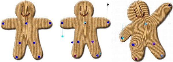
Figure 0. Image Warping
- Original sample from "Image Deformation Using Moving Least Squares" (blue markers part of the image)
- Dropped and Dragged Warping Points
- Result
Table of Contents
- Introduction
- Using the program WarpImage
- Some Background and links
- Structure of Project, ViewModel and Commands
- XAML/View for Image and Points
- Style for DragPoints: Templated Thumbnail and MVVM
- Transforming Image Coordinates to Bitmap Coordinates
- 2D pixel array from and to WPF image
- Rigid Point-to-Point Mean Least Square algorithm
- Simple Back Transformation with rectangular grid
- Points of interest
- License
Introduction
I was interested in transforming a static picture into a "moving" picture. I thought a point to point Image Deformation would be a useful start. I found the article: "Image Deformation Using Moving Least Squares", by Scott Schaefer, Travis McPhail and Joe Warren. However I did not find any C# code for the MLS algorithm so I wrote this C#/WPF hobby program (specialised demo, superficial testing, no optimisation of computing times). Possible points of interest for readers:
- First impression what point to point Image Warping can do.
- Simple example of creating and dragging (here: linked points) using templated thumbnails and MVVM.
- An example to access all the pixels in a 2D pixel array from/to a WPF image.
- A C# implementation of the rigid point-to-point MLS algorithm (without "pre-computation").
- Transformation of the Image using a simple Backward transformation.
I assume the reader is familiar with C#, WPF and the MVVM pattern. The applied MVVM pattern (not so strict or exemplary) is used for organising the code.
The article provides an example of a working solution/ minimal framework for the C#/WPF programmer who wants to have the advantages of WPF/XAML to make a nice UI and wants to perform a basic computation on all the pixels of an image.
In this article, I will use interfaces to present a compact global description of the code. The interfaces are not part of the code, I extracted the interfaces separately using SharpDevelop. For explanation purposes, I sometimes make some local functions global and introduced properties for variables.
Using the Program WarpImage

Figure 1. Program WarpImage, 2 screen shots using Warp Button mode.
See Figure 1 for two screen shots of the program. Left Image: specifying warp points,
Right Image: after warp. Points 1..12: give the man a larger coffee cup, 13-14 squeeze head, 15 more chin,
16-20 abs workout, 21-24 move brown kiwi, rest points anchor the rest of the image. Note the annotating capabilities of the connected points.
The program displays initially the image of file "Test.jpg" in the application directory or in the Images directory of the project. New images can be dropped from the file explorer. Points are created by left clicking on the image, by right clicking on a numbered point it is possible to delete the point using a context menu. All points can be cleared using the "Clear Points" button. A dropped warping point consists actually of a small anchor point, a numbered larger drag point to specify the desired position after warp and a connection/line between them. The anchor and drag points, also called Warping Points in the article, specify the warp.
The program has 2 modes: If "Use warp Button" is selected, the image from the original file is used and after pressing the "Warp Image", the image is warped. Before a new warp can be performed, the button "Reset Image" must be pressed. It is possible to modify the warping points. Use these buttons to toggle between original image and warped image.
In the interactive mode "Dragging a point" all anchor points are set to the position of the dragged big numbered points. Now a single point can be dragged and when released the Image Warping is performed on the existing Image. It can be used to fine-tune the transformation, but currently the image quality is deteriorated in each warp.
Pixels that are moved outside the WPF image are lost.
It should be noted that the MLS algorithm tries
the best way it can to match the specified warping points. Its freedom can/has to be constrained by adding some Warp Points that are not dragged to fix other parts of the image. If we specify one point only and drag it the whole image is translated. If we specify two points and we drag one, the whole image is globally "rotated". So if we want to make an object border thinner, we have to add some warping points without dragging to prevent a general translation. On the other hand, too many or extreme constraints cannot be solved.
My first observation is that on the sample of figure 0, the point to point transformation works
as expected. When applied in the figure 1, for example to enlarge the coffee cup, the point to point transformation is not appropriate. Several points must be used to specify the transformation, and in the result, the borders are distorted by the local point constraints. A somewhat better result can be obtained if we specify points at a larger distance, see the head. We stumbled on a fundamental context/resolution issue. From a practical viewpoint, it would be preferable to support (connected) line-to-line MLS transformation.
Some Background and Links
For reference, I give some of the most relevant bookmarks I stumbled upon in writing this program, I did not perform a systematic scan on Image Processing.
Note also that Image processing is not my (main) expertise.
For creating and dragging things, I found Dragging Elements in a Canvas and Annotating an Image in WPF by Josh Smits. I did not use adorners, see for example WPF Diagram Designer: Part 1 and MVVM Diagram Designer, where Sacha Barber introduced MVVM. My approach is inspired by Denis Vuyka's Blog WPF. Draggable objects and simple shape connectors. I started with a ListBox and an ItemTemplate with a Grid and ended with a ItemsControl and a Thumb.
For the more complex XAML binding, I always use the MSMD pattern: Monkey See Monkey do, or to stay with monkeys and Tarzan: me Google, you Google. Most standard questions are solved thanks to the WPF community. This community has always has a kind of "open source" attitude. I noted that an early version of VS2013 express for desktop did not produce a good old .exe. Now with the changes of Windows 8, all apps via the store, (VS moving to the cloud,) I am wondering if WPF is still a good "open source" hobby platform.
In the current application, we use batch processing: we get all pixels in a 2D array, process these and show the result. With a writeable bitmap also smaller parts of the image can be processed.
I only looked at WPF Windows.Media.Imaging very superficial. I found that working with WPF images with a minimal effort approach is not so straight forward due to the number of specialised bitmap classes, most are immutable (generated once and then not changeable) and due to lazy loading in some scenario's bits are not available.
Note that when working with pixels, it is always a question to work as simple as possible and stay close the system/software access to images at hand (32 byte?), or introduce float pixel arrays that are more accurate and no worries over the byte format. Another question is to write some filters yourself or use a better developed image library.
See for image deformation a Princeton lecture here.
The image warping gives similar issues as rotation and resizing, see for a popular introduction digital image interpolation.
For existing image warping C# code, see Warp images arbitrarily in C#, and CodeProject articles
like Image Processing for Dummies with C# and GDI+ Part 5 - Displacement filters, including swirl and Transforming Images for Fun: A Local Grid-based Image Warper and Image Warping Using Linear Interpolation and Double Buffer Panel.
One common approach is to use a Polynomial transformation of x,y coordinates to obtain certain effects.
I implemented from "Image Deformation Using Moving Least Squares" a simplified MLS algorithm using only the first 4 pages of the article. I used in the tile Image Warping instead of Image Deformation because this term was used in most C# articles.
For MLS code, I found Shape manipulation with Moving Least Squares for curves [w/ code] and a Matlab implementation.
Later, I discovered an existing program Fiji a distribution of ImageJ, Java and a lot of plugins - Including MLS.
However, implementing directly the equations from the article proved for me to be the most simple way. I expected the MLS algorithm to be more complex and find a good reason to dive into ILNumerics
or other libraries.
A forward transformation is well suited for transformation of the points of lines.
A forward transformation of pixel coordinates yields float coordinates. The resulting pixel coordinates are not by default on a rectangular grid, so the RGB interpolation of a pixel coordinate of the target image seems a little bit complex. For the image pixels, I decided to implement a backward transformation from target image pixel coordinates to original image pixels to keep things simple. The backward transform results in float coordinates too, but the nearest neighbour(s) of the regular rectangular pixels of the original image can be easily found to interpolate the RGB pixel value at those float coordinates. Advantages of a back transformation commonly mentioned are:
- Only pixel values that are in the target image are computed.
- They are computed once.
- There are no holes in the target image.
For image interpolation (Nearest Neighbour, Bilinear and Cubic), a lot of links can be found. I just came across Comparison of Interpolation Methods, Image Processing for Dummies with C# and GDI+ Part 4 - Bilinear Filters and Resizing, Quick image scaling algorithms, Linear interpolation past, present and future and Fastest RGB --- bilinear interpolation.
Structure of Project, ViewModel and Commands
The project is just a normal WPF project, see figure below. We have some files to support reading Images, some (MVVM) Utils, a Main ViewModel with Commands and MLSWarpImages.cs.
To give a global idea of the structure of the application we present the interface of the ViewModel and the commands, see code below. In the article, I will use Interfaces to present a compact global description of the code. The interfaces are not part of the code, I extracted the interfaces separately using SharpDevelop.
We see DragPoints, AnchorPoints and Connections that are used to specify the Warping Points and FileName, MainBitmap, ImageW and ImageH that are used to handle the Image.
Properties and commands will be bound to the View/XAML.
public interface IPointItem
{
double X { get; set; }
double Y { get; set; }
string Name { get; set; }
string Color { get; set; }
}
public interface IConnection
{
MyMainVm.PointItem Point1 { get; set; }
MyMainVm.PointItem Point2 { get; set; }
}
public interface IMyMainVm
{
ObservableCollection<MyMainVm.PointItem> DragPoints { get; set; }
ObservableCollection<MyMainVm.PointItem> AnchorPoints { get; set; }
ObservableCollection<MyMainVm.Connection> Connections { get; set; }
bool WarpOriginalOnCommand { get; set; }
bool NotWarpedYet { get; set; }
bool MyDebug { get; set; }
ObservableCollection<string> LogLines { get; set; }
string FileName { get; set; }
MyBitmap MainBitmap { get; set; }
double ImageW { get; set; }
double ImageH { get; set; }
Commands Commands1 { get; set; }
}
public interface ICommands
{
...
void SetAnchorsToDragPoints();
void AddNewPoint(double x, double y);
void SetToBitmapPixelCoord
(ref Point[] P, ObservableCollection<ViewModel.MyMainVm.PointItem> Points)
void OnDoWarpImage
(bool useImageFromFile, bool anchors2DragPoints);
ICommand ResetImage { get; }
ICommand SaveImage { get; }
ICommand ClearAll { get; }
ICommand AddTestPoints { get; }
ICommand DeletePoint { get; }
ICommand DoWarpImage { get; }
ICommand StartDragging { get; }
ICommand EndDragging {get;}
}
XAML/View for Image and Warping Points
Now we will discuss the View (MainWindow.xaml). We will focus on the part that is responsible for displaying the image and the specified Warp Points, see the XAML code below. A grid contains an Image and 3 ItemsControls. Since no GridRow or GridColumn is specified, all these components are rendered on top of each other, the Image is rendered first, the last ItemsControl last.
If we look at XAML for the Image, we see that the image source is bound to the MainBitmap.MyBitmapSource from the ViewModel. We will need ImageW and ImageH from the ViewModel to translate the Image coordinates to Bitmap coordinates. However, they cannot be directly bound to ActualHeight and ActualWidth of the image, because read-only Dependency Properties cannot be bound to a ViewModel variable (Oops??). Here we use the DataPiping for this data binding, see the answer of user Dmity Tashkinov to the StackOverflow question Pushing read-only GUI properties back into ViewModel.
If you look in the downloadable code, you will see that I use MVVM not strictly and there is some code behind in
MainWindow.cs. The
OnDragDelta event that we will discuss in the next section belongs there. The code for
MouseLeftButtonDown (I did some fact finding in the
View) and the file dropping events could be moved to the
ViewModel, but I am a little lazy.
<Grid>
<Image x:Name="myImage" Stretch="Uniform" Height="600" Width="600"
HorizontalAlignment="Left" VerticalAlignment="Top"
MouseLeftButtonDown="Grid_MouseLbdnNewPoint"
Source="{Binding MainBitmap.MyBitmapSource}" >
<u:DataPiping.DataPipes>
<u:DataPipeCollection>
<u:DataPipe
Source="{Binding RelativeSource=
{RelativeSource AncestorType={x:Type Image}}, Path=ActualHeight}"
Target="{Binding Path=ImageH, Mode=OneWayToSource}"/>
<u:DataPipe
Source="{Binding RelativeSource=
{RelativeSource AncestorType={x:Type Image}}, Path=ActualWidth}"
Target="{Binding Path=ImageW, Mode=OneWayToSource}"/>
</u:DataPipeCollection>
</u:DataPiping.DataPipes>
</Image>
<ItemsControl ItemsSource="{Binding Connections}"
Style="{StaticResource connectionStyle}"/>
<ItemsControl ItemsSource="{Binding AnchorPoints}"
Style="{StaticResource ancherPointsStyle}"/>
<ItemsControl ItemsSource="{Binding DragPoints}"
Style="{StaticResource dragPointsStyle}"/>
</Grid>
The warping points are represented by 3 ItemsControls. These are bound to the Connections, the AnchorPoints and DragPoints from the ViewModel and have a Style. We will discuss these ItemsControls, with a focus on the dragPointsStyle in the next section.
Style for DragPoints: Templated Thumbnail and MVVM
In this section, we will discuss the style of the ItemsControl that has the most complex style (dragPointsStyle). We discuss the style in more detail for 2 reasons, that could inspire the reader:
- It is easy to use this method to display for example a connected graph
- We have used in our
ViewModel a PointItem. However, using this method, it is also easy to define an ImageItem (that contains an image) and Create/Drop and drag these.
See the XAML code below for the style, I will only give a short description of the XAML code. To empathise the simplicity of XAML boilerplate code, we skipped some code such as the context menu:
- The style
dragPointsStyle defines an ItemTemplate. (Middle XAML code block) - The
ItemTemplate defines a DataTemplate. - The
DataTemplate is a Canvas with a Thumb. - The
Thumb has a Template: dragPointThumb (First code block). - This
ControlTemplate defines how a DragPoints Item is rendered: a context menu to delete the point, a coloured Ellipse and a Name (here: a digit).
<Window.Resources>
<ResourceDictionary>
<ControlTemplate x:Key="dragPointThumb">
<Canvas>
<Grid
Margin="-10"
<Grid.ContextMenu>
......
</Grid.ContextMenu>
<Ellipse Fill="{Binding Color}" Width="20" Height="20"
HorizontalAlignment="Center" VerticalAlignment="Center"/>
<ContentPresenter Content="{Binding Name}"
HorizontalAlignment="Center" VerticalAlignment="Center" />
</Grid>
</Canvas>
</ControlTemplate>
<Style x:Key="dragPointsStyle" TargetType="{x:Type ItemsControl}">
<Setter Property="ItemTemplate">
<Setter.Value>
<DataTemplate>
<Canvas>
<Thumb
Template="{StaticResource dragPointThumb}"
Canvas.Left="{Binding X, Mode=TwoWay}"
Canvas.Top="{Binding Y, Mode=TwoWay}"
DragDelta="OnDragDelta"
<!--Binding to DataContext see-->
u:Event2Command1.Command=
"{Binding Path=DataContext.Commands1.StartDragging,
RelativeSource={RelativeSource Mode=FindAncestor,
AncestorType={x:Type ItemsControl}}}"
u:Event2Command1.OnEvent="DragStarted"
...
u:Event2Command2.OnEvent="DragCompleted"
>
</Thumb>
</Canvas>
</DataTemplate>
</Setter.Value>
</Setter>
</Style>
<Style x:Key="connectionStyle" TargetType="{x:Type ItemsControl}">
...
<DataTemplate>
<Canvas>
<Line Stroke="{Binding Point1.Color}"
X1="{Binding Point1.X, Mode=OneWay}"
Y1="{Binding Point1.Y, Mode=OneWay}"
X2="{Binding Point2.X, Mode=OneWay}"
...
</ResourceDictionary>
</Window.Resources>
- Note that the
DataTemplate of the connectionStyle (Last code block) defines a line between the points of the Connection.
I will
discuss now some details of the Thumb. Because we have chosen a Canvas as ItemTemplate, we can access the attached dependency properties Canvas.Left and Canvas.Top. These are in XAML bound to the X,Y properties of the DragPoints item, so these are updated by the binding mechanism and visa versa. When dragged, the Canvas.Left and Canvas.Top are updated in the view in code behind by the OnDragDelta event handler, see code below. By using a Thumb ("made for dragging") and the DragDelta event we can robustly drag.
 private void OnDragDelta(object sender, DragDeltaEventArgs e)
{
  var thumb = e.Source as Thumb;

  var left = Canvas.GetLeft(thumb) + e.HorizontalChange;
  var top = Canvas.GetTop(thumb) + e.VerticalChange;

  Canvas.SetLeft(thumb, left);
  Canvas.SetTop(thumb, top);
}
The StartDragging and EndDragging commands are used for the interactive "Dragging a Point" mode. The DragStarted and DragCompleted events are bound in XAML to these commands using Event2Command (Oops!), an old solution from here. Use a MVVM framework from NuGet (Visual Studio: Tools..Library Package Manager), a Blend Behaviour or a NET 4.5 markup extension if you like.
Transform Image Coordinates to Bitmap Coordinates
A few coordinates can be tested by selecting the "Test Coord" checkbox and perform an Image Warp. In the Image directory, we copied some images with different DPI taken from another CodeProject for testing. We did not supply an image with a grid or images with a grid superimposed on it. It should be noted that the Image is always scaled. Currently, the Image is scaled Uniform given a fixed maximal Width and Height. When Scaling="None" is used and similar Image files are dropped with different DPI, the size of the rendered Image is different.
To transform the coordinates relative to the Image to coordinates in the Bitmap pixels, I use ImageW (bound to ActualHeight) and ImageH of the ViewModel and PixelWidth and PixelHeight from the MyBitmap.MyBitmapSource (discussed in the next section) of the ViewModel.
2D Pixel Array from and to WPF Image in Managed Code
The way we handle the WPF image is as follows. In the ViewModel, we have a MainBitmap. It is of type MyBitmap see code below for its interface.
It has a property MyBitmapSource, its setter always sends a notification. MyBitMapSource can be set/read from file by setting the FullName, or we can assign a new BitmapSource (or a WritableBitmap) to it. Because it is bound in the View/XAML to the view, changes will be shown.
public interface IMyBitmap
{
BitmapSource GetBitmapSource(string fullName, int thumbnailWitdh);
void SaveCurrentImage2File(string fullFileName);
string FullName { get; set; }
string ShortName { get; }
int ThumbnailWidth { get; set; }
BitmapSource MyBitmapSource { get; set; }
}
We are interested in processing all the pixels of the image.
The next thing is to get a 2D array of 4 byte pixels using managed code.
I re-used code from SideViewer, a simple image viewer with an experimental option to find double images that I wrote. First, we define a class for a pixel, see code below. We can access the whole Unsigned 32 bit Integer or just access a byte like pixel.Blue. The class is from answer of user
Dänu on the StackOverflow question Finding specific pixel colours of a BitmapImage.
[StructLayout(LayoutKind.Explicit)]
public struct PixelColor
{
[FieldOffset(0)]
public UInt32 ColorBGRA;
[FieldOffset(0)]
public byte Blue;
[FieldOffset(1)]
public byte Green;
[FieldOffset(2)]
public byte Red;
[FieldOffset(3)]
public byte Alpha;
}
Next, we have to copy the bytes from the BitmapSource to a PixelColor Array. We use code from the impressive answer from user Ray Burns from the already known StackOverflow question Finding specific pixel colours of a BitmapImage. The idea is to read from file or use an existing BitmapSource and set its format to PixelFormats.Bgra32. Next a 1D array can be obtained that can be transformed to a 2D 4-byte array or to 2D R,G,B float arrays. Indices of the 2D array are [iy,ix] so that the array can be used as input for a Writeable bitmap. See code below for snippets of functions from Image2PixelsArray.cs.
public static class Image2PixelArray
{
public static PixelColor[,] GetPixelsTopLeftFromFilename
(string _fileName, int DecodeHW = 0)
public static PixelColor[,] GetPixelsTopLeft(BitmapSource source)
private static void CopyPixelsTopLeft2
(this BitmapSource source, PixelColor[,] pixels)
public static int GetH(PixelColor[,] PixelsTopLeft)
public static int GetW(PixelColor[,] PixelsTopLeft)
public static WriteableBitmap BitmapSourceFromPixelsTopLeft
(PixelColor[,] PixelsTopLeft, double DpiX = 96.0,double DpiY = 96.0)
}
To go to a new Bitmap from a 2D PixelColor Array, we use a newly created WriteableBitmap. The WriteableBitmap.WritePixels accepts a PixelColor Array directly. Because we create a new BitmapSource, we might not need a WriteableBitmap. Note that a WriteableBitmap is normally used by a Lock, write a Rect in the BackBuffer and then Unlock. This looks certainly more appropriate when processing part of the image, but even in processing the whole image, it could be faster.
I did not systematically test this on all kind of Image formats but found no problems in some samples of coloured .Jpeg, .Gif and .Bmp images. Look for yourself if another Image format works by warping an image. I assume that if an image can be displayed, a Bgra32 formatting is possible. I vaguely recollect from the old days that image formats (.Tiff?) can support 4 origins (TopLeft etc.) and 2 xy scan line directions so I don't know if all those formats work as expected.
Rigid Point to Point Mean Least Square Algorithm
I will now discuss the implementation of the rigid MLS point to point Image Deformation from the article: "Image Deformation Using Moving Least Squares" without pre-computation. I just implemented the equations without understanding, quality testing and experimentation. The complexity of this part of the paper was implementation wise a little bit disappointing, this is a merit of the article. I will discuss the main equations I used in terms of the current implementation.
See for the equations the figure below. The first equation is the most important: it is the criterion that is optimised. Our AncherPoints will be p, DragPoints, the desired deformed positions, will be q. A MeshPoint of the original image will be v. (Note that in the next section we will change all that.) For every MeshPoint v we try to find one optimal transformation Lv. So per MeshPoint we have one optimal common transformation, but each mesh point (position v) has a different transformation. The optimal transformation is the one with the smallest weighted distance over all specified warping points i between the transformed AncherPoint and the desired position.
The second equation shows that the weights are different for each position v. The weight of the distance (transformed AncherPoint, Dragged PointItem) of a Warping Point i is, if we take alpha=1, reciprocal to the distance of the MeshPoint v to the AncherPoint i. Note that other weighting schemes are possible, like a more symmetrical "Gaussian" bar round the area of the p-q line or adapt the criterion to the N nearest neighbours.
All equations are very basic. See a constructed interface of the MeshPoint class in the code below:
public interface IMeshPointV
{
void ComputeTransformationParameters
(double _x, double _y, int _nPoint, Point[] _p, Point[] _q);
Point TransformL(Point p);
double X { get; set; }
double Y { get; set; }
int NPoint { get; set; }
Point[] P { get; set; }
Point[] Q { get; set; }
double[] W { get; set; }
double WSum { get; set; }
double PStarX { get; set; }
double PStarY { get; set; }
double QStarX { get; set; }
double QStarY { get; set; }
Point[] PHat { get; set; }
Point[] QHat { get; set; }
double M11 { get; set; }
double M12 { get; set; }
void ComputeW();
void Compute_pStar_qStar();
void Compute_pHat_qHat();
void ComputeM();
}
The rigid transformation is given by the bottom equation ((6) in the article). In the simplified Matrix computation I used no pre-computation, but I have directly normalised the Matrix, see code below. We only have to compute 2 elements of the matrix M. At a first glance all seems simple, but please report any errors.
private void ComputeM()
{
m11 = 0;
m12 = 0;
for (int i = 0; (i < nPoint); i++)
{
double a = pHat[i].X;
double b = pHat[i].Y;
double c = qHat[i].X;
double d = qHat[i].Y;
m11 = m11 + w[i] * (a * c + b * d);
m12 = m12 + w[i] * (a * d + b * -c);
}
double muNorm = Math.Sqrt(m11 * m11 + m12 * m12);
if ((muNorm < ToSmallHeuristic) || (nPoint == 1))
{
m12 = 0.0;
m11 = 1.0;
}
else
{
m11 = m11 / muNorm;
m12 = m12 / muNorm;
}
}
Given the original coordinates of the
AncherPoints (
p) and desired
DragPoints (
q) we can compute the local transformation for a
MeshPoint v by a call to functions
ComputeTransformationParameters(..) and
TransformL(..) from class
MeshPoint.
Simple Back Transformation with Rectangular Grid
Now, we want to construct the warped image. To keep things simple, we use a back transformation. For every pixel of the target image, we compute the (
float) coordinates in the original image. Next, we compute its nearest neighbours pixels in the original image. Using the (
float) coordinates and the RGB values of its neighbour pixels, we can use a linear or cubic interpolation to obtain the RGB value of the target pixel at the given (
float) coordinates.
For the back transformation of pixel coordinates of the target image, we call functions
ComputeTransformationParameters(..) and
TransformL(..). For the first function call, we now use
(..,DragPoints,AncherPoints) instead of
(..,AncherPoints,DragPoints) e.q we take
DragPoints for parameter _
p and
AncherPoints for parameter _q. (Note that due to the asymmetric distance in respect to
p and
q in the criterion this is not fully correct.)
We compute the back transformation only at MeshGrid points, we interpolate the transformed (x,y) coordinates of the other pixels in rows and between rows by a linear interpolation. See code below for the interface of class MovingLeastSquaresRectGrid. Function InitBeforeComputation(..) sets the internal variables and function WarpImage(..) computes the warped image.
public interface IMovingLeastSquaresRectGrid
{
void InitBeforeComputation(Point[] _p, Point[] _q, int _ImgH, int _ImgW, int stepSize);
WriteableBitmap WarpImage(PixelColor[,] Pixels, double DpiX, double DpiY);
int NPoint { get; set; }
Point[] P { get; set; }
Point[] Q { get; set; }
int ImgH { get; set; }
int ImgW { get; set; }
bool[] VXCompute { get; set; }
bool[] VYCompute { get; set; }
void SetXYCompute(int ImgH, int ImgW, int stepSize);
Point[] ComputeVAndInterpolateXYRow(int iy);
Point[] InterpolateXYRow(int iy, int iy1, int iy2, Point[] xyRow1, Point[] xyRow2);
PixelColor BilinearRgbInterpolation(PixelColor[,] PixelsOrg, Point coordOrg);
}
A point (ix,iy) is a MeshPoint if VXCompute[ix] and VYCompute[iy] are both true. The step size of the meshpoints does specify the detail of the warp/non linearity. In the main loop of function WarpImage(..) all rows are processed. The transformed coordinates of 2 successive rows with (VCYCompute[iy]==true) are computed using ComputeVAndInterpolateXYRow(iy). The latter function computes the back transformations for pixels ix where (VXCompute[ix]==true) and interpolates between them. InterpolateXYRow() is used to interpolate between the two successive rows where mesh points are computed.
In such a way, the transformed coordinates for all pixels of the target image are computed and finally function BilinearRgbInterpolation(..) is used to set the pixel in a PixelColor array. This array is finally written to a Writeable bitmap.
Points of Interest
- The program gives an first impression of
Point to Point Image Warping. - A simple sample of linked points is given and their annotation capability is show.
- One way to access a 2D array of pixels is given. Be free to implement your own algorithms.
- C# code of the rigid point-to-point MLS and a back transformation can be downloaded.
- The point to point warping performs as expected in some situations.
- Nearby points can result in local deformation of the image (Coffee cup example). We stumbled onto a context/resolution issue.
- It could be possible to store the (
x,y) translations of all mesh-points and apply a Gaussian filter on these to control the resolution. - Points are not always the best way to specify a warp.
- One solution is to implement line-to-line MLS. Another approach for such local deformations is the well know approach to introduce some
Polynomial Transformations of the pixel coordinates (
Enlarge, Shrink, Skew, etc.).
- In the interactive mode, the image quality deteriorates each iteration. Pixels that are not visible any more in the interactive mode are lost. An internal float representation could be introduced combined with a better (cubic) interpolation.
- Some large transitions can give some strange effects. Suppose we have a Warping Point (Anchor Point, Desired Drag position). In general after the warp, the object at the anchor point is displayed at the desired position. However the placements of other Warping Points can be of such nature that at its original position the object is also visible. This is counter-intuitive to the idea of a flow of moving pixels. Can we break large translations into smaller steps to prevent such effects?
History
- 2014-01-06. End of this project. Happy coding in 2014!
Retired hobby programmer.


 General
  News
News  Suggestion
  Question
  Bug
Bug  Answer
  Joke
Joke  Praise
  Rant
Rant  Admin
Admin 


