The FTDI FT232-family of chips are used everywhere. They offer a very compact way to interface an UART to an USB. As soon the USB devices started booming, the “huge” serial connectors began to disappear from our PC. However, many of us still needed a real-serial port, and FTDI had the genial idea to create a small chip to provide the conversion.
Our primary usage is RS485 to USB conversion, and we designed from scratch our adapter from the beginning. However, since we needed some extra features on the adapter itself, we added a small MCU together with the FT232 chip. Let’s say the “dirty work” of cleaning the noise incoming from the RS485 line was made by the MCU, then its result is sent through the FTDI chip to the PC, via USB. Our systems are typically placed in very noisy environment, long cabling, poor grounding and so away. For this reason, even dealing with a lot of noise, we had never particular problems with such a structure. No problems so far…until the past week!
The Problem
Consider any protocol you like over a UART: it’s typically structured as a BOM (begin-of-message) and some kind of EOM (end-of-message). Let’s take it easy, considering that there’s no noise in the message itself, but immediately before or after. That’s not an abuse, because the RS485 line is placed in a low-impedance state only during the byte transfer. When released, it’s in a high-impedance state, and a lot of noise is appearing on the line. So, what do you expect from a false byte (due to the noise) immediately after the useful message? I’d expect an error after, and maybe some random bytes after the data. By the way, since we’re using a well-defined BOM+EOM, we’re able to detect the start and the end of the message, then cut off any false byte before and after. Our surprise was seeing the false bytes…in the middle!
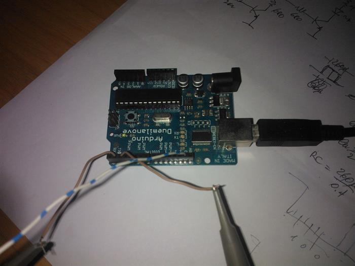
For making you understand better the case, I take my old Arduino 2009 and simply plug it to my PC. It’s an original Arduino, without any hack, and the scope probes are just for inspecting what happens.
The Arduino is running this very minimal sketch. It’s just sending a string of bytes, continuously, interleaving a short delay. If you notice, the “noise” is intentionally placed right after the end of the stream, as a byte sent with the wrong parity. The expectation is receiving a “frame error”, but maybe the correct value.
#define PARITY true
void setup()
{
pinMode(2, OUTPUT);
}
void loop()
{
digitalWrite(2, true);
Serial.begin(38400, SERIAL_8E1);
delay(10);
for (byte i = 0; i < 0x60; i++){
Serial.write(i);
}
Serial.flush();
delayMicroseconds(500);
#if PARITY
Serial.begin(38400, SERIAL_8O1);
Serial.write(0x12);
Serial.flush();
#endif
digitalWrite(2, false);
delay(200);
}
Now, here is the counterpart running on the PC, which receives the data and logs them on a file (or on the console).
class Program
{
const string FileName = @"C:\Temp\arduino_dump.txt";
static void Main(string[] args)
{
bool exit = false;
byte[] buffer = new byte[1024];
using (var port = new SerialPort("COM3", 38400, Parity.Even, 8, StopBits.One))
{
port.Open();
port.ErrorReceived += port_ErrorReceived;
while (exit == false)
{
int count = port.BytesToRead;
if (count > 0)
{
port.Read(buffer, 0, count);
var sb = new StringBuilder();
for (int i = 0; i < count; i++)
{
if (buffer[i] == 0) sb.AppendLine();
sb.AppendFormat("{0:X2} ", buffer[i]);
}
File.AppendAllText(FileName, sb.ToString());
}
if (Console.KeyAvailable)
{
exit = true;
}
else
{
Thread.Sleep(1);
}
}
}
}
static void port_ErrorReceived(object sender, SerialErrorReceivedEventArgs e)
{
Console.WriteLine(e.EventType);
}
}

When the programs run, the log collects the received data and it’s pretty clear where the problem is.
00 01 02 03 04 05 06 ... 4A 4B 4C 4D 4E 3F 3F 4F 50 51 52 53 54 55 56 57 58 59 5A 5B 5C 5D 5E 5F 12 00 01 02 03 04 05 06 ... 4A 4B 4C 4D 4E 4F 50 3F 3F 51 52 53 54 55 56 57 58 59 5A 5B 5C 5D 5E 5F 12 00 01 02 03 04 05 06 ... 4A 4B 4C 4D 4E 4F 3F 3F 50 51 52 53 54 55 56 57 58 59 5A 5B 5C 5D 5E 5F 12 00 01 02 03 04 05 06 ... 4A 4B 4C 4D 4E 4F 50 51 3F 3F 52 53 54 55 56 57 58 59 5A 5B 5C 5D 5E 5F 12
Note: The strings have been shorted for clarity.
As expected, the extra byte appears always at the end of each string: simply the FT232’s UART accepts the 8-bits value as-is, despite the wrong parity. However, the real problem is before the extra byte: there is a strange 3F-pair in the message. Why? Who adds it?
Let’s Dig Into..
First off, the MSDN docs about the SerialPort state that the 3F is added by the framework, upon the ParityReplace property. That is, when this property is set to zero (disable parity replacing), the 3F-pair disappear. Yes, but I wouldn’t lose that info, and…why the parity error is revealed a bunch of bytes before the actual wrong byte?
My colleague made several tests:
- a serial stream using the “old” RS232
- a serial stream using a commercial RS232-to-USB NOT-using a FTDI chip
- a serial stream using a commercial RS232-to-USB using a FTDI chip
It was pretty easy to understand that the odd-placement of the 3F-pair was observed only in the FTDI case.
As he was performing the tests, I decided to make my own with the Arduino, which is shown above. However, I wanted to understand why, so I moved to some research. FTDI does not offer any specs about the FT232 USB protocol. However, there’s always an angel in the sky, and this angel actually wrote a small C-library which claims to interface Windows/Linux without any problem to the FT232-family chips. Browsing the driver sources, I bumped against the status poll, which also transfers the data from the chip to the PC. Here is some remark found in the sources:
/**
    Poll modem status information

    This function allows the retrieve the two status bytes of the device.
    The device sends these bytes also as a header for each read access
    where they are discarded by ftdi_read_data(). The chip generates
    the two stripped status bytes in the absence of data every 40 ms.

    Layout of the first byte:
    - B0..B3 - must be 0
    - B4       Clear to send (CTS)
                 0 = inactive
                 1 = active
    - B5       Data set ready (DTS)
                 0 = inactive
                 1 = active
    - B6       Ring indicator (RI)
                 0 = inactive
                 1 = active
    - B7       Receive line signal detect (RLSD)
                 0 = inactive
                 1 = active

    Layout of the second byte:
    - B0       Data ready (DR)
    - B1       Overrun error (OE)
    - B2       Parity error (PE)
    - B3       Framing error (FE)
    - B4       Break interrupt (BI)
    - B5       Transmitter holding register (THRE)
    - B6       Transmitter empty (TEMT)
    - B7       Error in RCVR FIFO
So, something gets clearer:
- The UART error are summarized as-per-chunck of data, not just for each byte
- The incoming data should face a bit-2 equals to ONE because the forced parity error
I am FAR to be an expert of USB protocols, and of course you would have many USB devices exchanging data. Listening to what’s up in the circus may be a challenge. The first thing to do is inspecting the Windows registry for the VID/PID codes of the FDTI chip. Here is how to do:
To inspect the USB data, the simplest things to do is downloading the really awesome tool provided by Microsoft: Messaging Analyzer. It does almost everything (excluding coffee), and it’s also free.
In order to limit the number of the message displayed, but let’s apply a simple (even dumb) filter to the grid. The results are as follows. This first picture shows the last chunk of the string when there’s NO the extra byte. You may notice that the status byte has the bit-2 off.
The second snapshot shows the altered transfer, instead. The status byte has now the bit-2 on.
Conclusions
The reason behind the odd-placement is now clear: a design-decision of the FTDI engineers. However, seems that there’s no way to overcome this problem. The only thing you can do is disable the ParityReplace in the SerialPort, and forget any UART error. This implies you strictly rely the reliability of the message on the protocol itself, because the physical layer won’t help you much.
Played with transistors and ICs before being ten. First approaches to programming (PET Commodore) in the early '80.
Then AppleSoft, TurboPascal, Assembler and VisualBasic.
Currently employed at CET Electronics as lead software developer, involved in creation of industrial control systems.
Loving graphics technologies, I had some great time with SVG.
Since 2006 my primary language is C#, where I am focusing on WPF.


 General
  News
News  Suggestion
  Question
  Bug
Bug  Answer
  Joke
Joke  Praise
  Rant
Rant  Admin
Admin 


 Have a 5!