|
Assuming the connections are proper, the backlite should work if power is present. Are the character segments doing anything (I'm guessing it's a 16x2 or similar)? It's been my experience that the segments 'get slightly darker' when power is applied, regardless of backlite. Also, there's the contrast voltage to consider.
"the debugger doesn't tell me anything because this code compiles just fine" - random QA comment
"Facebook is where you tell lies to your friends. Twitter is where you tell the truth to strangers." - chriselst
"I don't drink any more... then again, I don't drink any less." - Mike Mullikins uncle
|
|
|
|
|
jeron1 wrote: It's been my experience that the segments 'get slightly darker' when power is applied, regardless of backlite
Thank you! That's helpful.
It's not doing anything - it's as dead as fish, meaning I've either wired it catastrophically wrong or it came dead on arrival. I've checked the wiring many times, so at this point I'm kind of at a loss.
It's why I wanted to know if anyone knew how to simply get power to thing just so I can prod it for signs of life.
Real programmers use butterflies
|
|
|
|
|
Does turning the pot from one extreme to the other do anything noticeable?
"the debugger doesn't tell me anything because this code compiles just fine" - random QA comment
"Facebook is where you tell lies to your friends. Twitter is where you tell the truth to strangers." - chriselst
"I don't drink any more... then again, I don't drink any less." - Mike Mullikins uncle
modified 2-Oct-20 13:33pm.
|
|
|
|
|
Nope. I even tried wiring/shorting around the pot but nothing.
Real programmers use butterflies
|
|
|
|
|
The pot is for contrast so you generally can't go around it (unless you're using fixed resistors). The fact that the backlite does nothing, is suspicious like there's no voltage. Without a multimeter it's difficult say, you wouldn't happen to have a discrete LED and a 1K resistor, that you could use as a kind of 'voltage' probe?
"the debugger doesn't tell me anything because this code compiles just fine" - random QA comment
"Facebook is where you tell lies to your friends. Twitter is where you tell the truth to strangers." - chriselst
"I don't drink any more... then again, I don't drink any less." - Mike Mullikins uncle
|
|
|
|
|
Yeah but I'm not sure which pins i need to check. I think i know which are the data pins, but the control pins labels aren't very clear. It's why I was hoping someone could tell me at minimum, which of the 16 pins on this apparently standard LCD interface I need to wire up to show signs of life.
Real programmers use butterflies
|
|
|
|
|
I would check pins 1 and 2, generally pin 1 is ground and pin 2 is 5v, if you don't have this nothing else matters. Similarly, pin 16 is ground for that backlite and pin 15 is the current limited 5v input for the backlite.
"the debugger doesn't tell me anything because this code compiles just fine" - random QA comment
"Facebook is where you tell lies to your friends. Twitter is where you tell the truth to strangers." - chriselst
"I don't drink any more... then again, I don't drink any less." - Mike Mullikins uncle
|
|
|
|
|
Thank you! I'll give that a whirl.
Real programmers use butterflies
|
|
|
|
|
honey the codewitch wrote: I've either wired it catastrophically wrong or it came dead on arrival
If you bought it off of ScamBay then this could be the problem. Selling broken electronics is a huge thing on the auction sites. I avoid the batteries too... I saw a clear pattern from multiple sellers where they would sell me 50% good batteries and the other half bad.
I've got some really good stories to tell about ScamBay... I once bought some flood lights off the site. I bought eight of them and the seller only sent me six. He fought me in the dispute and I suddenly realized that I could use the FedEx package weight to prove that it was impossible that the shipment contained 8 of them.
Best Wishes,
-David Delaune
|
|
|
|
|
Got it new off amazon. Only concern is it is a knockoff made my elegoo and not an arduino branded kit. It was a lot cheaper so if i have to order a replacement LCD screen I'm probably still money ahead.  Although that's not taking into account the aggravation of testing an LCD screen for signs of life. Although that's not taking into account the aggravation of testing an LCD screen for signs of life.
Real programmers use butterflies
|
|
|
|
|
If it's elegoo then really don't worry, they are one of the better ones, and consistantly much of thier gear is of really high quality.
I have a number of elegoo products, and to date I've never had a problem with any of them. In fact I find the cheep bundled Arduino Uno clones are often better constructed than the original ones and half the price!
|
|
|
|
|
First thing to do: Check your wiring, especially ground and the supply voltage. If that does not help, get yourself the datasheet of the display (the one that you have, not the one you assume you have!). I have had such things before. in my case it was a MAX232 Rs232 level shifter. I wired it up according to the datasheet from Texas Instruments and the output voltage levels were not anywhere near RS232 specifications. Then I got the original datasheet and one of the external capacitors was indeed connected to ground instead of VCC. Now it actually works.
Edit: Have you tried to read something from the display's registers instead of writing? This way you might cut some corners. I would also take a look at the signals with my oscilloscope, but I assume you don't have one just waiting for something to do...
I have lived with several Zen masters - all of them were cats.
His last invention was an evil Lasagna. It didn't kill anyone, and it actually tasted pretty good.
modified 2-Oct-20 14:29pm.
|
|
|
|
|
|
Grrr, yes it is one of those 16 pin interface LCDs. I think you're probably right that it's a bad jumper wire or something. I guess I need to go ahead and order a multimeter. I just overlooked it when i got the kit.
Real programmers use butterflies
|
|
|
|
|
Get yourself the datasheet and take a good look at the pinout of that connector. Never assume anything. Guessing never helps.
I have lived with several Zen masters - all of them were cats.
His last invention was an evil Lasagna. It didn't kill anyone, and it actually tasted pretty good.
|
|
|
|
|
I know that the pinout is a de facto standard 16 pin interface for small LCDs like this. I don't need to assume anything about it. I just need to get it to respond.
A multimeter will help. A datasheet won't solve my current issue.
Real programmers use butterflies
|
|
|
|
|
And some guy in China never heard of your de facto interface or had his own ideas. Are the signals at least labeled on the display's board? That would help a little, even without the datasheet.
I have lived with several Zen masters - all of them were cats.
His last invention was an evil Lasagna. It didn't kill anyone, and it actually tasted pretty good.
|
|
|
|
|
They're labeled, but not in way that's helpful.
Let me put it this way. The LCD is either the standard hitachi interface for it, just like the one the genuine arduino has, or it's just garbage because exactly one person knows how to use it and that's the person that designed it. if that's the case, no datasheet exists.
So datasheets still aren't the solution.
Real programmers use butterflies
|
|
|
|
|
Why don't you make a pic or two and post the links? I think that might help people to help you.
M.D.V. 
If something has a solution... Why do we have to worry about?. If it has no solution... For what reason do we have to worry about?
Help me to understand what I'm saying, and I'll explain it better to you
Rating helpful answers is nice, but saying thanks can be even nicer.
|
|
|
|
|
Good idea. But I've since dismantled the circuit. I'll try again later today.
Real programmers use butterflies
|
|
|
|
|
*SIGH* What a noob!
honey the codewitch wrote: They're labeled, but not in way that's helpful.
You mean unmeaningful stuff like VSS, VDD, V0, RS, RW, E, D0 - D7? These don't tell you anything? Are you painting by numbers (= blindly following some examples)?
VSS is the source voltage, or ground. VDD is your supply voltage (probably +5V). Mess these up and your display will be sending smoke signals and die. Check these.
Vo, if I remember right, is not an input. It's a voltage that's produced in the display from the supply voltage. You are supposed to use a potentiometer to regulate the display's contrast. You should not take my word for it and check this in the datasheet.
RS is a digital input to select one of two registers in the display. What are the registers for? Don't
know, but you can always check the datasheet. In any case, you must make sure that only an output pin of the Arduino is connected here and is set to the correct value (0 or 1), depending on which register you want to access.
RW is the read/write signal, oldschool 6800 style. 1 if you want to read the selected register and 0 if you want to write to it. A datasheet would tell you that. It's another input, so it must be hooked up to yet another output pin of the Arduino.
E is the enable signal, also old 6800 style. It's also an input, so you will need another output pin from the Arduino here.
D0 - D7 are your eight data bits. You will need eight bidirectional signals from the Arduino, or if it does not have such data lines, reconfigure these I/O pins to the right direction for every access of the display. Here you can easily send both the Arduino and the display to east hyperspace when you read from the display and the Arduino's I/O pins are still set to be outputs. Here you should read up on how the Arduino handles bidirectional parralel data lines and make sure that such a collision never happens. Short two outputs together and you get a nice short circuit which will fry a few transistors and permanently damage your devices.
A and K are simple. They are the anode and cathode of the LED that lights the display. You only need to hook them up to +5V and ground with a resistor to limit the current. Which value? Ask the data sheet. It will tell you the maximum current that is allowed and Ohm's law will tell you the rest. Just guessing, but a typical single LED works nicely with a 470 Ohm resistor in series. I have some that survived more than 40 years that way.
I have lived with several Zen masters - all of them were cats.
His last invention was an evil Lasagna. It didn't kill anyone, and it actually tasted pretty good.
|
|
|
|
|
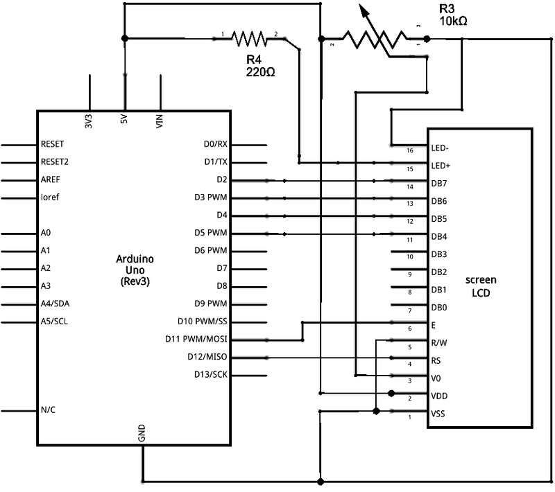
A lot of that jibes with what the schematic suggested. I think you're right about V0 for example.
The short answer is no, I don't know what I'm doing. I used to build simple circuits when I was little. After that I took up programming. I've never taken classes or read books about this.
Eventually I got this Arduino and here I am. So I'm learning.
*steps off your lawn*
Real programmers use butterflies
|
|
|
|
|
Ok, let's try it a different way, then.
I assume you use a small breadboard to wire everything up. Ignore the wiring guide for the breadboard. Use a schematic instead, like this one[^]. I hope this is the right one, please check that.
First you should understand howw to use a breadboard[^]. It's not really hard to understand, but you do not want to produce shorts or unwanted connections.
First you hook up the voltages. VSS or GND are ground, VCC, VDD or +5V are typically supply voltages. V0 is a special voltage that is provided by the display. It's an output, not an input, so you do not have to worry about it right now. You must be very careful with voltages. You can really fry your hardware when they are reversed. Double and triple check everything before ever switching it on.
Now you can take care of the backlight. Here you can do less harm, but you have the additional complication of having to use external potis and resistors. Just follow the schematic and check your wiring then it will be ok. The A and K signals might also be labled as LED+ and LED-.
RW is simply tied to ground (aka VSS). That means you can only write to the display and not read anything. That's good, because this way the display will never use D0 - D7 as outputs and a collision with the Arduino's I/O pins is impossible.
The Arduino does not have the old 6800 bus signals. It's a microcontroller that has to emulate these signals on its general I/O pins. Let's assume for now that the little software library you have does this correctly. On the hardware side it's relatively simple. You must hook up the right Arduino signal to the right signal of the display, as shown in the schematic. On the Arduino side you will have signals named D0 - D(whatever). These are the general I/O pins. They have nothing to do directly with D0 - D7 on the display. Don't confuse them. They are different signals that just happen to use similar naming conventions. Just follow the schematic and the labels on the connectors. Do not go by pin numbers, because they may not be as standardized as we would like them to be. Once you have wired up the display's RS, E and D0 - D7 signals to the right Arduino signals you are almost done.
Last thing to do: Check everything. This is debugging. Question everything, rethink everything and make sure that everything as it should be. Assume nothing. Just like debugging software.
Good luck.
I have lived with several Zen masters - all of them were cats.
His last invention was an evil Lasagna. It didn't kill anyone, and it actually tasted pretty good.
modified 2-Oct-20 20:23pm.
|
|
|
|
|
Thank you! This is even more than enough information for me to tinker with. I greatly appreciate it.
Real programmers use butterflies
|
|
|
|
|
I don't want to spoil your fun, but this is not playing with Lego and it will never be. It's programming and you know how far cut and paste solutions will get you. The real trophy here is not getting that display to work. It's learning why it does not work right now and learning from it. You should know how addictive that can get once you get a taste of accomplishment. Just ask Tom Hanks[^].
I have lived with several Zen masters - all of them were cats.
His last invention was an evil Lasagna. It didn't kill anyone, and it actually tasted pretty good.
|
|
|
|


 General
  News
News  Suggestion
  Question
  Bug
Bug  Answer
  Joke
Joke  Praise
  Rant
Rant  Admin
Admin 


