
Getting Started with the Intel® Edison board on Windows
4.79/5 (5 votes)
In this guide, you’ll connect to the Intel® Edison board through a terminal and update the firmware on your board.
Get access to the new Intel® IoT Developer Kit, a complete hardware and software solution that allows developers to create exciting new solutions with the Intel® Galileo and Intel® Edison boards. Visit the Intel® Developer Zone for IoT.
Overview
- In this guide, you’ll connect to the Intel® Edison board through a terminal and update the firmware on your board.
- For more information on Intel® Edison:
Intel® Edison Product Brief (Specs)
Cool projects built with Intel® Edison
Requirements
- Intel Edison board
- Intel Edison breakout/expansion board (Arduino or similar)
- 2 Micro B to Type A USB cables
- OR
- 1 Micro B to Type A USB cable and 7-15V DC supply
Assemble your board
At the end of this section, you should have an assembled Intel Edison board.
- Place the Intel Edison board within the white outline on your expansion board, lining up the holes on the Intel Edison board with the screws on the expansion board.
 Figure 1. Intel Edison board lined up with expansion board
 - Press down on the Intel Edison chip just below the words "What will you make?" until you feel a snap.
 Figure 2. Intel Edison board installed on expansion board
 - Use the two hex nuts to secure the module to the expansion board. Hand-tighten the hex nuts onto the two screws that protrude through the Intel Edison board.
 Figure 3. Intel Edison board secured with hex nuts
 - If your expansion/breakout board has plastic legs or spacers, fasten the spacers to the board.
Connect the board to your system
At the end of this section, your Intel Edison board will be connected to your computer via USB cable and powered either through the USB cable (Option A) or through a DC supply (Option B).

Note: If you are going to use more power-intensive features, such as WiFi, the mini servo, or an Arduino shield, using a 7 to 15V DC input is recommended.
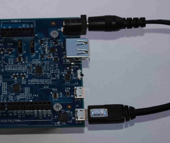
The Intel Edison board has three USB ports:
The middle port (Micro A type) as shown on the Arduino expansion board, is used for the following:
- Power through USB
- Ethernet over USB
- Uploading Arduino sketches
- Updating the firmware by using the board as a storage device, like a flash drive
The edge port (Micro A type) is used to create a terminal connection by serial over USB only.

Option A: Power through USB
- For Arduino expansion board: Find the microswitch SW1 (shown below) in between the larger and smaller USB ports on the expansion board. Ensure the microswitch is switched towards the micro-USB (smaller) ports.
Note: If you intend to use the USB Female A Type port to connect a peripheral in the future, the microswitch should be switched towards the USB Female A Type port.
 Figure 7. Intel Edison board with the microswitch switched toward the micro USB ports
 - Power up the board, as follows:
- Plug in one of the micro-USB cables to the middle USB connector on the expansion board.
- Plug in the other end of the USB cable to your computer.
- A green light should light up on the expansion board. If it doesn't, check your connection.
- Wait a moment for the board to boot up. You will know that the board is fully initialized when your computer mounts a new drive (much like inserting a SD card into your computer).
- Plug in your second USB cable to the edge USB connector on the board.
Note: If you do not see a new drive, and the LED light (DS1 on the Arduino expansion board) is occasionally turning on and off, it is likely that the board isn’t getting enough power from the USB port. Plug in your AC adapter (if you’re on a laptop), try a different USB port on your computer, or try using a USB hub that has a power supply.
Option B: Power through DC plug
- Plug in the DC power supply to the DC plug on your expansion board. You should see a green light from the board indicating it has power.
- Plug one of the micro-USB cables into the edge USB connector on the expansion board.
- Connect the other end of the USB cable into your computer.
Install driver
At the end of this section, you will have the Intel Edison board connected to your computer as a COM port.
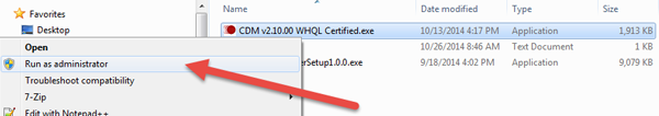
- Download the FTDI driver: www.ftdichip.com/Drivers/CDM/CDM%20v2.10.00%20WHQL%20Certified.exe.
- Right-click the .exe file you downloaded, which should be called "CDM…" and select Run as Administrator:
- Click Extract.
- Click Next.
- Click Finish.
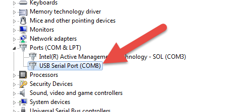
- You should see a new USB Serial Port entry in the "Ports (COM & LPT)" section of the Device Manager. Make note of the number next to "COM", as highlighted below.
Connect to the Intel Edison board
At the end of this section, you will have connected to the board using PuTTy, and updated your firmware.
- Download the PuTTY terminal emulator: http://the.earth.li/~sgtatham/putty/latest/x86/putty.exe.
- Double-click the putty.exe file you downloaded to run it.
- At the top right of the Putty Configuration dialog box, specify the following:

- For Connection type, select the Serial radio button.
- In the Serial Line field, type the COM # (e.g.
COM7) of your board. - In the Speed field, type
115200. - From the side menu, expand the Connection options and select Serial. Specify the following settings:
- In the Serial line to connect to field, type the COM # (e.g.
COM7) of your board. - In the Speed (baud) field, type
115200. - In the Data bits field, type
8. - In the Stop bits field, type
1. - From the Parity drop-down list, select None.
- From the Flow control drop-down list, select XON/XOFF.
- If you wish to save your setup, click the Session category on the left. Type a name for the configuration in the Saved Sessions field, then click Save.
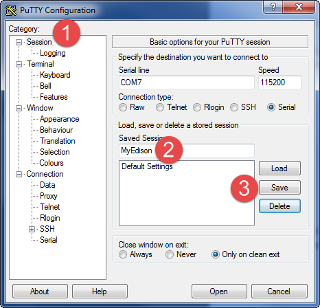
- Click Open to connect to the board.
- When you see a blank screen, press the Enter key twice. A login screen is displayed:

- At the login prompt, type
rootand press Enter. - Press Enter when prompted for a password. The following screen is displayed:

- It is highly recommended you flash your firmware to get the latest features and important updates. To do so, follow the instructions on the Flashing Edison (wired) - Windows page, then continue with the steps below.
- Configure your username, password, and WiFi options by entering the command:
configure_edison --setup. Follow the on-screen instructions to create a username, password, and so on.Notes:
- If you get a "configure_edison: not found" error, you need to update your firmware on the Flashing Edison (wired) - Windows page.
- To configure your WiFi use this Edison WiFi network guide
- Once you have configured your username, password, and WiFi options, enter the command:
ifconfig. Make note of your "wlan0" IP address, as shown in the figure below.