
IoT Device for Predicting and Identifying Problems in a Datacenter
4.67/5 (4 votes)
Automation with Arduino Prototype for an Alarm Device based on Audiometric Sounds Pattern Control
1. Introduction
In recent times, the use of technology in the various corporate environments has ceased to be something desirable to become something necessary. More and more companies, from the most diverse sectors, have taken competitive advantages with the application of technology. For this reason, one of the sectors that has most gained criticality in these corporations is the hardware technology department.
Companies that still have control over their network infrastructure, servers, and personal computers live in constant turbulence regarding the availability of their operation. That is, the smooth running and continuity of technology operations is what keeps the company's business processes running. Many times, even the availability of these computing services are tied to agreement policies and fines, demonstrating the importance and formalism of these processes for the business.
In this context, the ideal scenario for any corporation that depends on a computing infrastructure is that there are no failures in the availability of these services. However, faced with this utopia, companies live with the incessant search for quality models and processes to improve their maintenance and support techniques for computing services. One of these areas is the anticipation of impending hardware problems.
2. Objective and Methodology
This project aims to develop an alarm system that monitors ambient sound in a computer infrastructure department of an organization. As audiometry readings outside the considered standards are identified, the system automatically identifies the possible cause and sends notifications to the area manager, including its reading history, so that the technical manager can anticipate possible infrastructure problems.
As this project involves multidisciplinary knowledge applied to technology in a general purpose scenario, it is important to consider a real laboratory that allows the understanding and the real experience of a corporation with real routine problems and needs and support from professionals with their various specialties. For this reason, collaborative activities were performed with follow-up and participatory tasks in all stages throughout the project.
As a case study, the work had as a partner an automotive parts manufacturing company composed of ten production plants, three distributors, and a research center. To integrate these units and sectors, the company counts on a very robust computational and communication network infrastructure. Considering that the logical and physical maintenance and management of these machines are done by the company itself, it provides a very interesting and complete scenario for analysis and testing for this project.
From the technical point of view, in the proposed process, the system will monitor the audio sensor and send the reading to a Microsoft Excel spreadsheet (figure 1). From this information base (control sheet), the analysis component will make comparisons with the collected data, validating them with previous files (history) and calibration information (settings and learning). Based on these comparisons, the system makes a decision about the need to alarm.
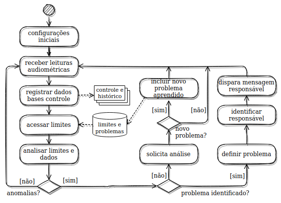
This decision must consider the limits defined in the unique setup files for a given execution context; if it exceeds the pre-set values, the message sending will be triggered from Microsoft Excel's Visual Basic for Applications and support from some instant messaging communication platform.
The support as tools, modules and technologies involved in this project includes, like following:
Automation Items
- Arduino Leonardo R3 Compatible
- Voice Recognition Module V3
- Electret Max9814 Amplifier Module with Automatic Gain Control
- KY-038 Sound Sensor Module
- ESP8266 Wi-Fi Module ESP-01
- Adapter for Wi-Fi Module ESP8266 ESP-01
- 5V Relay Module
- Led 5mm High Brightness
Support Tools
- Virtual Decibilimetro App (Google Play Store: April 2020)
- Excel Visual Basic for Applications (Microsoft Office, April 2020)
- Tinkercad: online tool for prototyping and drawing
- Photoshop CS6 Portable v13.0: image editing software
- Blynk mobile application - IoT for Arduino
- Arduino1.8.12: IDE for developing the Arduino application
3. Development
A very important step for the project was the noise analysis phase in the environment used as laboratory. In this stage, it was necessary to monitor the environment for a few days, so that it was possible to define an audiometric "normality" standard for the data center. Also at this stage, it was necessary to simulate problems, for example, a blocked cooler, inoperative ventilation, among others, so that reproducible problems could be recognized already during the study phase.
Figure 2 shows two test readings performed with the aid of an audiometry application (Decibelimeter, 2020), on an Android phone. Through these tests, it is possible to verify the increase in the sound level when a piece of equipment has a problem that generates some kind of sound. On the left side (figure 2.a) is represented the level in a normalized environment, without any problems, presenting only noise emissions within the expected standards. In (figure 2.b) is represented the increase in sound level when performing a simulation of a problem, in this test was simulated an equipment with a problem in the cooler.
 |  |
After the audiometric analysis and noise simulation activities, the circuit design was built. Figure 3 represents a prototype of the circuit structure for process automation. This prototype was built in the online tool Tinkercad and Photoshop CS6 Portable (Monk and Laschuk, 2017). According to this project, the system does monitoring in two ways:
- through the sound sensor modules, connected to the terminals of the Arduino (Javed and Adas, 2017), as follows:
VCCof the module to the5Vof the Arduino,GNDon theGNDof the Arduino, the output of one of the modules on analog inputA0, controlling low levels and the output of the other module on analog inputA9, controlling high levels . - through the voice recognition module, its differential is in the fact that the module is trained to recognize the sound generated by certain previous problems.

The circuit also has a wi-fi module controlled through the online platform Blynk. This module is connected to the Arduino and is responsible for controlling the relay used to pause and release the sending of messages (alarm triggering). The three leds at the bottom of the prototype are auxiliary and indicate the possible states: (green) message sending released, (orange) message sending paused, and (blue) off. The paused and released states are controlled via the online platform Blynk (2020), while the off state is controlled by a mechanical switch.
void setup() {
  pinMode(pinPause, INPUT_PULLUP);
  pinMode(pinBreck, INPUT_PULLUP);
  Keyboard.begin();
  pinMode(10, OUTPUT); //Pino do Led Verde (Ligado)
  pinMode(16, OUTPUT); //Pino do Led Azul (Pausa Envio de Mensagens)
  pinMode(14, OUTPUT); //Pino do Led Vermelho (Desligado a Leitura de Som)
}
The function in C language code for Arduino is responsible for controlling the input values of the analog ports A0 and A9 of the Arduino, respectively connected to the sound sensor outputs. The test was performed in order to check and regulate the sound level in the environment through the sound modules.
void nivelSom() {
  while (cont < 10000) {
      recebeValorSensor = analogRead(pinoSensorSom_Um);
      valor_Dois = analogRead(pinoSensorSom_Dois);

     if (valor_Dois>recebeValorSensor){
         recebeValorSensor = valor_Dois;
     }

    if (recebeValorSensor > valorMaior) {
        valorMaior = recebeValorSensor; //Quarda o Maior Valor Leitura no Loop
    }
     cont++;
  }

    cont = 0;
    tensao = valorMaior / 1023.0 * 4.54;
    dB = 87.1 * tensao - 144, 4;

  if (dB < 0) {
      dB = 0;
  }

   Keyboard.print(dB);
   teclaEnter();

  if (dB > 58||dB < 42) {
      delay(45000); //Aguarda o Envio da Mesagem (Não Faz Leitura do Nível de Som)
  }

  valorMaior = 0;
  delay(100);
}
This function is responsible for data treatment with the convert equation, and following with the insertion into the table history and control, through "void problema()"
Figure 4 shows code loaded into the Arduino module works according to the following algorithm:
- The voltage level value generated by the sound module is converted to an approximate value in decibels and sent to the control spreadsheet in Microsoft Excel.
- Simultaneously, if any pattern changes have been identified, the voice recognition module sends to the Arduino at the pin corresponding to the change mapped on the logic level.
- Only in this case, the Arduino recognizes through a condition which pin specifically has its state changed and sends the code corresponding to the problem detected to Microsoft Excel.

Figure 5 represents the control screen built in Microsoft Excel, responsible for storing the values in decibels for history and controlling the sending of notifications (messages). In this spreadsheet, the values in decibels and codes sent by the Arduino are received in a single cell, which is monitored by Visual Basic for Applications. The value is analyzed and if it corresponds to a predetermined code, referring to a problem, then the function responsible for opening the Google Chrome browser is called, and then the instant messaging platform to send a message with the description of the problem to those responsible for the IT sector. On the other hand, if the value received is not a code referring to some identified problem, but a value in decibels out of the predefined normality range is recognized, the value will be stored in the spreadsheet with the date and time of the reading and a message will be sent, alerting the detection of a problem of unknown origin, for further analysis. After investigation, in case the alert is considered a problem not yet mapped as expected treatment, the rates recorded in the history can then be entered into the system, causing the speech recognition module to be trained to recognize this type of problem for future occurrences.

4. Problems
One of the biggest problems faced in the development of the system was to get the reading in decibels as accurately as possible. This problem was only solved by putting a second module of the type: "Max9814 Electret Microphone Amplifier with Automatic Gain Control". This resulted in a more precise reading, a higher gain response and less loss.
The second problem faced was how to recognize the possible causes of the problems. With the sensor models already defined, several readings of the sound level were taken to collect the maximum, average and minimum values in an environment with normal operation, without any problems, other tests were made simulating some common problems. This analysis helped to identify the increase of the sound level in several problems, but it was still very imprecise to indicate the cause of the problem, because there are very close values between some types of problems. To solve this problem, along with the sound sensors, a voice recognition module V3 was also used, this module was trained to recognize some types of problems already found previously, while the voice recognition module is checking the existence or not of some problem already known, the sound sensor files some anomaly in the sound level, which will be analyzed later and if necessary the voice recognition module will be trained to recognize eventually.
5. Results
Figure 6 shows the system already assembled on the printed circuit board, with all the components. The conclusion of the system presented satisfactory results, because the objectives for this step were achieved, it managed to meet the pre-established requirements, obtain the reading of the sound level in decibels and the recognition of a problem in the monitored environment. Once the discrepancy in the sound level was recognized, the system sent the reading to a Microsoft Excel spreadsheet, which in turn filed the values and sent a message through the messenger platform to the group responsible for analyzing and acting on the notified problems.

The test environment for the built prototype is the central server of the company used as a case study, in its São Paulo unit. It is a rack for servers with cooling by cooler, containing several types of equipment, and not only the equipment will be monitored, but also the rack itself with its parts, cooler, door opening, oscillations in the structure, among other possibilities. The results were as expected, considering that the prototype was able to identify all simulated cases: normality, predefined problems and unmapped anomalies.
Figure 7 demonstrates the execution of the system in the field test environment. In it, you can see the results of the tests for sending a message from a messaging application on the screen of a cell phone registered as the contact of a person responsible for a specific area. Moreover, because it is a system capable of checking the sound level, monitoring whether or not the level is within the limits established for the environment, there is the possibility of using the system in other applications, even in other types of environments, such as environments where it must be kept the minimum noise possible, alarming messages if they exceed the limits or performing certain specific tasks by voice commands.

6. Conclusion
It was a challenge to develop an automation system from conception to deployment and testing in a real environment. Involving a real context as a practical laboratory allowed advantages during problem understanding, analysis and refinement of objectives, and support for testing activities. However, among the main benefits with the completion of this project are non-technical gains, such as maturity regarding the complete life cycle of a system, management decision making, collaboration, and corporate involvement.
As a research result, the major contribution of this project is to identify problems quickly, something that common monitoring systems cannot do so quickly. An example would be the problem with the cooler; while this prototype relies on sound pattern monitoring to recognize a potential problem, common temperature monitoring systems only recognize the problem after overheating.
As a suggestion for future work, we propose the study of the implementation of a module that makes recordings of suspicious audiometric patterns of the system and the implementation of modules for other types of controls and reference, such as: temperature, humidity and presence sensor, among others, also proposes the creation of an application for control and monitoring in real time and with good accuracy.
Acknowledgments
Special thanks to the Taranto Comercial Group, Imp. e Exp. Ltda., (Buenos Aires, Argentina), especially to Eric Barbosa de Carvalho; without such collaboration and support it would not have been possible to develop this project; mainly regarding the technical orientations of context and presentation of real problems. This partnership allowed for more precise specifications and better results during the field validations.
References
- Blynk (2020). "Blynk - IoT for Arduino, ESP8266 / 32, Raspberry Pi." Available on the web at https://play.google.com/store/apps/details?id=cc.blynk. Accessed August 1, 2020.
- Decibelimeter (2020). "Virtual Decibelimeter," Android App. Available on the web at https://play.google.com/store/apps/details?id=com.gamebasic.decibel. Accessed April 18, 2020.
- Cláudio L. V.O, A. (2018). “Aprenda Arduino uma abordagem prática sketches” ed. 1; Ed. Copyright, 2018
- Cristiano Nazário (2020). “Automação Profissional com Arduino”, Curso online. Disponível na Udemy: https://www.udemy.com/course/automacao-profissional-com-arduino-completo/, 2020
- Javed, A.; Adas, C. J. (tradução) (2017). “Criando projetos com Arduino para internet das ciosas”; ed.1, Ed. Novatec Editora, 2017.
- Luiz Gustavo (2020). “Automação Residencial por Comandos de Voz – Módulo 1”, Curso online. Disponível na Udemy: https://www.udemy.com/course/automacao-residencial-por-comandos-de-voz-modulo-1, 2020
- Michael McRoberts; (2015). “Arduino Básico” ed. 2; Ed. Novatec Editora, 2015.
- Monk, S.; Laschuk, A. (tradução). (2017). “Programação com Arduino: começando com sketches” ed. 2; Ed. Bookman, 2017.
- Oliveira, S.; (2017). “Internet das coisas com ESP8266, Arduino e Rasspberry PI”, ed.1, Ed. Novatec Editora, 2017.
- Teixeira, R. (2020). “Introdução à Engenharia com Arduino”, Curso online. Disponível na Web em: https://www.udemy.com/course/introducao-a-engenharia-com-arduino/.
- Tinkecad (2011). Site para design de hardwares eletrônicos (on-line). Disponível em https://www.tinkercad.com. Acessado em 17 de maio de 2020.
- Vitor Amadeu Souza; (2020). “Envio de E-mail com o módulo SIM800L para medição de Decibelímetro Programado no Arduino”, ed.1, Ed. Cerne, 2020.
- WhatsApp Web (2020).“Aplicativo para desktop”. Disponível em. Acessado em 18 de maio de 2020.
History
- 18th July, 2021 - Document creation
- 19th July, 2021 - Textual revision, initial version
- 20th July, 2021 - Layout and images revision and validation
- 21st July, 2021 - Submission