
Examples of Layered Application Architecture Based on the Use of Sublayers Sets and a Hierarchy of Data Models
3.81/5 (7 votes)
This article will look at examples of layered architecture for different types of applications.
1. Application Data
Application data is located in data models, data containers and can be loaded from external data sources.
1.1. Application data model is a collection of data structures and operations for processing them.
1.2. Application data containers:
- visual forms displaying application data
- internal application data resources – text, XML, images, binary files; files with application settings, files with application metadata, files with data resources for internationalizing
- data streams in data transfer channels used by the application
1.3. External data sources are data resources and external applications.
1.3.1. External applications are data stores (persistence data stores, infrastructure data stores).
They perform the function of data storage. Examples of data stores are server databases, FTP servers, directory services, email storage systems.
1.3.2. External applications are transient data sources. They are not data stores. Transient data sources retrieve data from persistence data stores, from other transient data sources or generate data using their own business logic algorithms. Examples are web services, message queues.
1.3.3. Data resources are operating system resources (OS registry data, OS and hardware settings, USB/COM/LPT ports), local files and shared files in the local network, including desktop databases files.
1.4. Application data groups.
Application data groups are facade application data, internal application data, external application data and data at application boundaries. See figures 2-4.
2. The Single-Tier Application Schema and Structure
2.1. The structure of the single-tier application consists of 3 main groups:
- The functionality of layered group consists of a set of isolated layers; each layer implements functions specific to it; interaction occurs unidirectionally between adjacent layers.
- The functionality of cross-cutting group can be used by all application layers.
- The functionality of dataflow group uses data mapping operations to transfer data between application data models, data binding operations to bind data between the data model and the visual interface, data serialization operations to serialize / deserialize data during data exchanging with other applications via the data transfer channel; data exchange is bi-directional; the functionality of the dataflow group defines the boundaries of using data models in the application.
2.2. The single-tier application can be presented in the form of two schemes:
- Schema of interaction between application layers
- Schema for transferring data between application data models, a scheme for binding data of a data model and data in controls of a visual interface, a scheme for serializing / deserializing data during data exchanging with other applications via a data transfer channel.
3. Using Layered Architecture in Single-Tier Application
The functionality within the n-layered (n>1) architecture are organized into horizontal layers. Each layer has a specific role and responsibility within the application. Each layer has one or more data models associated with it. The layer functionality can be implemented both in separate specialized classes and as methods in data model classes.
Facade layer is used as a facade for accessing application functionality from other tier of n-tier application or from other applications.
Logic layer implements the application logic.
Persistence layer implements the functionality of access to persistence data stores.
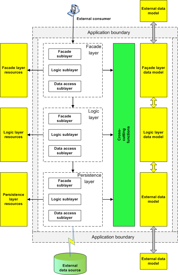
4. Application Layer Structure
Each layer of an application consists of a set of sublayers - façade sublayer and one or more functional sublayers. A sublayer is a functional block that implements a set of functional operations.
Facade sublayer is a functional block that implements a layer facade and using which the layer's functionality is accessed by the higher application layer.
Logic sublayer is a functional block that implements the logic of the layer.
Data access sublayer is a functional block that implements access to external data sources.
5. Multi-Tier Application
Multi-tier application consists of a set of single-tier applications and external data sources. Each tier can be implemented on a separate software platform. For example: tier 1 - Java, tier 2 - JavaScript + Angular
In 3-tier application, tier 1 is focused on working with external consumers, and tier 2 is focused on working with business logic and external data sources.
Tier 3 is external data sources.
6. Relation Between Application Layer and Data Model
The functionality of each layer uses one or more data models. In some cases, a data model can be used by multiple application layers.
7. Relation Between Application Layer and Data Resources
The functionality of each layer uses data resources specific to it.
7.1. For the facade layer, these are the OS registry, files with application settings, files with resources and application metadata, USB / COM / LPT ports.
7.2. For the logic layer, these are business data file stores - for example, XML and CSV files.
7.3. For the persistence layer, these are desktop databases.
8. Data Exchange Between Application Layers and Application Tiers
8.1. CLR objects (for Microsoft.net platform) or Java objects (for Java-applications) are used for data exchange between application layers.
8.2. Data transfer objects are used for data exchange between the tiers of a multi-tier application or between different applications. The main data formats of data transfer objects are XML and JSON.
9. Types of Functional Operations
Application functionality is implemented as a set of operations.
Operations are the interface of the sublayer and provide access to sublayer functionality from an higher sublayer, higher layer or external application.
9.1. View logic operations are used by visual form controls.
9.2. Presentation logic operations implement the logic of the facade layer.
9.3. Application logic operations implement application-specific business rules and coordinate the operations of business logic and external data access and are a facade for accessing the functionality of the logic layer.
9.4. Domain logic operations implement the application-independent business rules.
9.5. Query operations implement the functionality for selecting data from persistence data stores. They represent the query part in the CQRS principle.
9.6. Command operations implement the functionality for changing data in persistence data stores. They represent the command part in the CQRS principle.
9.7. Data transfer operations are used during data exchanging with external data sources.
9.8. Persistence façade operations are a facade exposes a coarse-grained interface to access persistence layer functionality from the higher application layer.
9.9. Persistence logic operations are implementation of the logic for working with data in persistence data stores.
9.10. When reading / writing local data resources, the application uses OS data read / data write functions.
10. Façade Layer Structure and Functionality
Façade layer is used to interact with external consumers of application data. Data consumers are users and other applications. Façade layer consists of façade sublayer, logic sublayer and data access sublayer.
Façade sublayer:
- for GUI applications implements a visual interface, which is a set of visual forms
- for web-services implements a data transfer interface that provides external data consumers access to a web service through data transfer channel
- used to call presentation logic operations
Logic sublayer:
- implements presentation logic operations for interaction between façade layer and application logic in logic layer
- for example, this is a set of controllers in ASP.NET MVC technology.
Data access sublayer is used in the façade layer in the case when there is no logic layer in the application. Implements query, data read / write and data transfer operations.
11. Logic Layer Structure and Functionality
Logic layer implements application logic. Logic layer consists of façade sublayer, logic sublayer and data access sublayer.
Façade sublayer:
- entry point for calling logic layer functionality from façade layer
- checking user access rights to logic layer functionality
- implements a general error handling algorithm in the logic layer
- manages transactions in command operations in data access sublayer
- input data validation in command operations in data access sublayer
- input data validation and output data filtering in domain logic operations in logic sublayer
- logging of operations in logic layer
Logic sublayer implements domain logic operations.
Data access sublayer implements the query, command, data read / write and data transfer operations.
12. Persistence Layer Structure and Functionality
Persistence layer is used to work with persistence data stores. Persistence layer consists of façade sublayer, logic sublayer and data access sublayer.
Façade sublayer is a facade to access persistence layer functionality from the higher application layer. Façade sublayer can be implemented using data access object pattern.
Logic sublayer is an implementation of the logic for working with data in persistence data stores. ORM frameworks can be used in the logic sublayer. When using direct sql queries, the logic sublayer can use persistence manager objects.
Data access sublayer is used to interact with persistence data stores. Data access sublayer is a set of database connection objects that, when interacting with a database, use the functionality is implemented in ODBC / JDBC drivers and OLE DB providers.
13. Relation Between Operations and Application Layers
| Sublayer / boundary | Objects / interfaces | Operations | Data | Comment |
| Façade layer | ||||
| Application boundary | visual interface | data are displayed in visual forms | for GUI applications | |
| data transfer interface | data stream | for web-services | ||
| Façade sublayer | visual forms | view logic operation | view model | for GUI applications |
| web-service objects (server-side part of web-service) | data transfer operations for interaction with external consumers | internal data transfer model | for web-services | |
| Logic sublayer | view presenters | presentation logic operation | view model | for GUI applications |
| data transfer presenters | presentation logic operation | internal data transfer model | for web-services | |
| Data access sublayer | persistence services | query operation | persistence model | for external data sources such as persistence data stores |
| directory services | data transfer operations for interaction with directory services | directory data model | for external data sources such as directory services (LDAP, Active Directory) | |
| message services | data transfer operations for interaction with web-services and message brokers | external data transfer model | for external data sources such as transient data sources | |
| OS data read/write functions | data read/write operations for interaction with external data sources such as files and OS resources | data stream | for external data sources such as files and OS resources | |
| Logic layer | ||||
| Façade sublayer | application logic objects | application logic operation | domain model | |
| persistence model | ||||
| external data transfer model | ||||
| Logic sublayer | domain logic objects | domain logic operation | domain model | |
| Data access sublayer | persistence services | query operation | persistence model | for external data sources such as persistence data stores |
| persistence services | command operation | persistence model | for external data sources such as persistence data stores | |
| directory services | data transfer operations for interaction with directory services | directory data model | for external data sources such as directory services (LDAP, Active Directory) | |
| message services | data transfer operations for interaction with web-services and message brokers | external data transfer model | for external data sources such as transient data sources | |
| OS data read/write functions | data read/write operations for interaction with external data sources such as files and OS resources | data stream | for external data sources such as files and OS resources | |
| Persistence layer | ||||
| Façade sublayer | data access objects | persistence façade operation | persistence model | |
| Logic sublayer | ORM-frameworks, persistence manager objects for direct sql-queries | persistence logic operation | persistence model | |
| Data access sublayer | database connection objects | data transfer operations for interaction with sql server databases | external data transfer model | for persistence data stores such as sql server databases |
| database connection objects | data transfer operations for interaction with desktop databases | external data transfer model | for persistence data stores such as desktop databases | |
| Application boundary | network interface | data stream | for persistence data stores such as sql server databases | |
| OS data read/write functions | data stream | for persistence data stores such as desktop databases |
14. Examples of Layered Application Architecture
Taking into account the set of used operations and types of external data sources, it is possible to describe a set of basic application architectures.
14.1. Common Application Architecture
14.2. Schemes for Transferring Data Between Data Sources and Data Consumers


14.3. Application Architecture Examples


15. Relation Between Use Case and Application Architecture by the Example of Heat Exchanger Calculating
Use case consists of one or more scenarios. Each scenario is a list of steps required to complete a use case.
For relation the step of the use case scenario with the application functionality, it is necessary to introduce the concept of a unit of application logic.
Unit of application logic is an element of the application logic functionality used in the use case scenario (this is application logic operations in façade sublayer logic layer).
If the functionality of the application is designed using a set of use cases, then as a result of the design, we get a set of units of application logic that implement the functionality of the entire set of use cases of this application.
If the command pattern is used to implement the unit of application logic, then all use cases of the application can be described using a set of objects of the command type. Each unit of application logic will be implemented using a separate command object.
The command pattern fits perfectly with goal to explicitly represent the use cases defined by business logic into application code.
Consider the heat exchanger calculation using GUI application as use case scenario.
The heat exchanger calculation algorithm can be implemented as a walk through a set of visual forms. On the first form, the user enters the initial data for the calculation, on the last form, the calculation results are displayed. On each form, one or several units of application logic are called.
Step 1. User opens Form 1 where the initial data for calculating the heat exchanger is entered. This is the unit of application logic 11 (retrieving a set of reference data from the database used in the heat exchanger calculation algorithm).
Step 2. On Form 1, user enters the initial data and starts the calculation algorithm. This is the unit of application logic 21 (the heat exchanger calculation algorithm is started; then the list of calculated heat exchangers is saved in the database).
After the end of the calculation, form1 is closed and form2 opens with a list of calculated heat exchangers. This is the unit of application logic 22 (retrieving a list of calculated heat exchangers from the database).
Step 3. On Form 2, user selects a suitable heat exchanger and goes to Form 3 to view its parameters. This is the unit of application logic 32 (information about the selected heat exchanger is entered into the database).
Form 2 closes and Form 3 opens with a set of parameters for the selected heat exchanger. This is the unit of application logic 33 (retrieving the selected heat exchanger parameters from the database).
Step 4. On Form 3, the user views the parameters of the selected heat exchanger. When Form 3 is closed, all unselected heat exchangers will be deleted from the database. This is the unit of application logic 44.

Therefore, use case scenario is determined by the functionality of the set of application logic units. Façade layer can be implemented using various technologies, but the functionality of the application logic units will remain unchanged.

History
- 28th October, 2020: Initial version
- 24th November, 2020: Chapters 9, 12, 13 edited