
Implementation and Testing of Universal, Reversible Fredkin Gates
5.00/5 (6 votes)
Apr 2, 2020
10 min read
16609
220
Implementation of Fredkin gates using standard TTL ICs, and their testing with an Arduino Uno microcontroller board
Introduction
Fredkin gates were introduced by Edward Fredkin and Tommaso Toffoli in their paper titled “Conservative Logic” (International Journal of Theoretical Physics, 21 [3-4]: pp. 219-253). The following figure shows the symbol for a Fredkin gate (left) and its functionality (center and right).

The input signal u acts as a control, whereas the input signals x1 and x2 are data. The output signals are v, y1, and y2. From the functional description, v is always identical to u. When v = 1, the outputs are identical to the inputs (y1 = x1, and y2 = x2). When v = 0, the outputs correspond to the inputs swapped (y1 = x2, and y2 = x1). Hence, when the control signal v is 1, the Fredkin gate implements a SWAP operation.
Fredkin gates are universal because they can be used to implement any logic function, as illustrated in the following figure, where AB is logical AND, A + B is logical OR and A’ is logical NOT.

Fredkin gates are also reversible because the SWAP operation is its own inverse. If the output signals (v, y1, y2) of a Fredkin gate are connected, respectively, to the input signals (u, x1, x2) of a second Fredkin gate, the output signals of the second gate are identical to the input signals of the first gate. The reversibility of the SWAP operation can be demonstrated by the following simple Unmanaged C++ (Win32) console application program, which implements the operation both as a macro and as a function.
// Implementation and testing of the self-inverse 'swap' operation
// both in terms of a macro and a function.
//
// Programmer:  Jorge L. Orejel
//
// Last update: 03/30/2020
//
// Based on:    Intel 80X86 and Motorola 68000 assembly code and Borland
//              C++ code written in 1991.

#include "stdafx.h"

#include <stdio.h>

// Macro implementation of 'swap' operation.
//
#define SWAP( x, y ) { x ^= y; y ^= x; x ^= y; }

// Functional implementation of the 'swap' operation
//
void Swap( int *x, int *y )
{
   *x ^= *y;
   *y ^= *x;
   *x ^= *y;
}// Swap

void Display_int_x_y( int x, int y )
{
   printf( "\nx == %d, y == %d\n\n", x, y );
}// Display_int_x_y

void DisplayIntSWAP( int x, int y )
{
   printf( "SWAP( x, y ): x == %d, y == %d\n", x, y );
}// DisplayIntSWAP

void Display_char_x_y( char x, char y )
{
   printf( "\nx == '%c', y == '%c'\n\n", x, y );
}// Display_char_x_y

void DisplayCharSWAP( char x, char y )
{
   printf( "SWAP( x, y ): x == '%c', y == '%c'\n", x, y );
}// DisplayIntSWAP

void DisplaySwap( int x, int y )
{
   printf( "Swap( x, y ): x == %d, y == %d\n", x, y );
}// DisplaySwap

int _tmain( int argc, _TCHAR* argv[] )
{
   int x = 333, y = 666;
   char chX = 'A', chY = 'z';

   Display_int_x_y( x, y );
   SWAP( x, y );
   DisplayIntSWAP( x, y );
   Swap( &x, &y );
   DisplaySwap( x, y );

   Display_char_x_y( chX, chY );
   SWAP( chX, chY );
   DisplayCharSWAP( chX, chY );
   SWAP( chX, chY );
   DisplayCharSWAP( chX, chY );

   printf( "\n" );
   return 0;
}// _tmain
Observe that departing from the usual textbook code that uses a temporary variable, the preceding program implements the SWAP operation by applying the exclusive-or (XOR) operator (‘^’ in C/C++/C#) three times. When executed, the program produces the following output. (Observe also that, unlike the Swap function, the SWAP macro can be applied to any scalar data type.)
x == 333, y == 666

SWAP( x, y ): x == 666, y == 333
Swap( x, y ): x == 333, y == 666

x == 'A', y == 'z'

SWAP( x, y ): x == 'z', y == 'A'
SWAP( x, y ): x == 'A', y == 'z'
Press any key to continue . . .
Fredkin gates are not just a theoretical exercise on the design of logic gates, for they have important applications both in reversible computation and quantum computation.
Implementation of Fredkin Gates
The following figure shows the functional operation of Fredkin gates in terms of ordinary logic operations, where a bar on top of a signal name denotes negation (NOT), two signals together denote conjunction (AND), and the encircled plus sign denotes the exclusive-OR (XOR) operation.

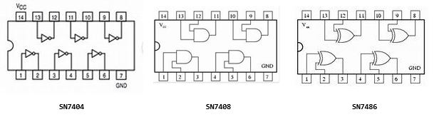
The output signals Q and R of the Fredkin gate in the preceding figure can be implemented with the standard TTL ICs 7404 (Hex Inverters), 7408 (Quad AND Gates), and 7486 (Quad XOR Gates). The pin assignments for these TTL IC chips are as follows.
The following two figures show the implementation of two Fredkin gates. Fredkin Gate A is the first one, with inputs C (control), A and B (data) and outputs C, A’, B’ (the quote marks do not indicate negation). Fredkin Gate B is the second one with inputs C (control), A’ and B’ (data) and outputs C, A, and B. The data outputs of Fredkin Gate B are labeled to indicate the fact that if the outputs of Fredkin Gate A are fed, as described before, to the inputs of Fredkin Gate B, the outputs of gate B are identical to the inputs of gate A. The light-emitting diodes (LEDs) have no part number. They are ordinary miniature LEDs (the rectangular yellow LEDs are 7 mm in length, and the round green and amber LEDs are 5 mm in length). In the physical implementation, shown after the gate diagrams, the LEDs connected to the outputs A’ and B’ of Fredkin Gate A were omitted. Observe that the LEDs are connected in negative logic: if a signal is logic 0, the LED connected to it will be ON, whereas if the signal is logic 1, the LED will be OFF. The labels for the output signals of the NOT, AND and XOR gates are written in the C/C++/C# format for Boolean (bool) expressions.
Fredkin Gate A

Fredkin Gate B

Physical Wiring of Two Fredkin Gates in Cascade
The following image shows the wiring of two Fredkin gates on a proto board. From the left, the four TTL IC chips are: one 74LS04 (Hex Inverters), two 74LS08 (Quad AND Gates), and one 74LS86 (Quad XOR Gates). The “LS” designation stands for “Low-Power Schottky” but this version of TTL ICs does not make a design difference when compared to the non-LS version of the ICs.

The rectangular, yellow LED and the two round green and amber LEDs on the left of the proto board show, respectively, the state of the inputs C, A and B to Fredkin Gate A. The yellow, green and amber LEDs on the right show the state of the outputs C, A’ and B’ of Fredkin Gate A. Those signals are connected, respectively, to the inputs C, A’ and B’ of Fredkin Gate B. The round green and amber LEDs between the second 74LS08 and the 74LS86 IC chips show, respectively, the A and B output signals of Fredkin Gate B, which should be in the same state (ON or OFF) as the green and amber LEDs connected to the A and B inputs to Fredkin Gate A, thus showing the reversibility of Fredkin gates. (Due to the lack of connecting holes on the proto board, the rectangular yellow LED corresponding to the output of Fredkin Gate B was not connected.) The proto board was powered with a Belker Universal AC Adapter model PA-30120W-ZMX.
Manual Testing of the Fredkin Gates
The following eight images show the state of all LEDs for the eight possible combinations of the input signals (C, A and B) of Fredkin Gate A. Recall that the LEDs operate in negative logic: if a signal is logic 0, the LED connected to it is ON, whereas if the signal is logic 1, the LED is OFF. The logic values of the signals, and the action performed by the gates, are given at the top of each image.
C = 0, A = 0, B = 0 (no SWAP)

C = 0, A = 0, B = 1 (no SWAP)

C = 0, A = 1, B = 1 (no SWAP)

C = 0, A = 1, B = 0 (no SWAP)

C = 1, A = 0, B = 0 (SWAP)

C = 1, A = 0, B = 1 (SWAP)

C = 1, A = 1, B = 1 (SWAP)

C = 1, A = 1, B = 0 (SWAP)

The negative-logic states of the LEDs in the preceding eight images demonstrate the correct wiring and the expected operation of the reversible Fredkin gates: the outputs A’ and B’ from Fredkin Gate A are the swapped values of its inputs A and B, while the outputs A and B from Fredkin Gate B are the swapped values of its inputs A’ and B’ and are identical to the inputs to Fredkin Gate A.
Automated Testing of the Fredkin Gates
In order to automate the testing of the Fredkin Gates, the inputs to Fredkin Gate A (C, A, and B) were connected, respectively, to the input-output digital lines 13, 12 and 11 of an Arduino Uno microcontroller board. The ground (GND) line of the board was connected to the ground rail (”‒“) of the proto board. The following image shows the connections.

The Arduino Uno board was attached via a USB cable to a Dell Inspiron mini laptop as serial port COM4. Later on, due to problems accessing the COM ports with Windows 10 Home and Windows 7 Ultimate and Professional on three other laptops, the board was attached to port COM3 of a Toshiba Satellite laptop running Windows 10 Pro. (The states of the rectangular yellow and round green and amber LEDs on the proto board correspond to the inputs C = 1, A = 0, B = 1 to Fredkin Gate A.) The Arduino IDE was used to write the following C++ Sketch to drive the inputs to Fredkin Gate A.
// Computer:         Toshiba Satellite C55D-B5308 laptop.
// Operating system: Windows 10 Pro.
// Compiler:         Arduino 1.8.2.
//
// C:\Users\Jorge\Documents\Arduino\Fredkin Gates\Fredkin\Fredkin.ino

// C++ Sketch program to test the circuit implementing two Fredkin
// gates connected in cascade.
//
// Programmer:  Jorge L. Orejel
//
// Last update: 04/01/2020 : Execution on a Toshiba Satellite C55D-B5308 laptop.
//
//      03/25/2020 : Original coding and execution on a Dell Inspiron laptop.
//

int C = 13; // Control pin
String Cname = "C";
int A = 12; // Data A pin
String Aname = "A";
int B = 11; // Data B pin
String Bname = "B";

void setup()
{
   pinMode( C, OUTPUT );
   pinMode( A, OUTPUT );
   pinMode( B, OUTPUT );
   digitalWrite ( C, LOW );  // Inactive state
   digitalWrite( A, HIGH );
   digitalWrite( B, HIGH );
   Serial.begin( 9600 );
} // Setup

void TogglePin( int pin, String pinName )
{
  int state = digitalRead( pin ), _state;

  Serial.print( pinName );
  Serial.print( ": " );
  Serial.print( state );
  Serial.print( " -> " );
  Serial.print( !state );
  digitalWrite( pin, !state );
  Serial.println();
} // TogglePin

void SetPin( int pin, String pinName, int newState )
{
  int currentState = digitalRead( pin );

  if ( currentState != newState )
  {
    if ( newState == 0 )
    {
      digitalWrite( pin, LOW );
    }
    else
    {
      digitalWrite( pin, HIGH );
    }
    Serial.print( pinName );
    Serial.print( ": " );
    Serial.print( currentState );
    Serial.print( " -> " );
    Serial.print( newState );
    Serial.println();
  }
} // SetPin

void loop()
{
  if ( Serial.available() > 0 )
  {
    Serial.println( "---------" );
    delay( 4000 ); // Delay 4000 microseconds (4 seconds)
    TogglePin( C, Cname );

    for ( int i = 0; i < 2; ++i )
    {
      delay( 3000 );
      SetPin( A, Aname, i );
      delay( 3000 );
      SetPin( A, Aname, !i );
      for ( int j = 0; j < 2; ++j )
      {
        delay( 3000 );
        SetPin( B, Bname, j );
        delay( 3000 );
        SetPin( B, Bname, !j );
      }
    }
  }
} // loop
The preceding C++ Sketch simulates the manual testing of the Fredkin gates for all the combinations of the input signals (C, A, and B) to Fredkin Gate A. After connecting the Arduino board to a USB port on the computer, the selection of Tools->Port in the Arduino IDE allows the specification of the COM port to which the board is attached. The selection of Sketch->Verify/Compile runs the C++ compiler to verify errors. The selection of Sketch->Upload transfers the error-free compiled code to the Arduino flash memory. The selection of Tools->Serial Monitor opens the Serial Monitor window showing a display area (to which the output from the commands Serial.print and Serial.println is sent) and a button labeled Send. Clicking on the button will start the C++ Sketch, running the Setup function once and then the loop function indefinitely until either the function executes exit( 0 ) or power is disconnected from the Arduino board. The execution of the preceding C++ sketch produces the same states of the LEDs obtained with the manual tests.
Automated Testing of the Fredkin Gates by a C# Program Communicating With a C++ Sketch Running on the Arduino Board
The two Fredkin gates can also be tested from the .NET framework by a C# program communicating via a serial (COM) port with a suitable Arduino C++ Sketch such as the following. (The calls to the library function delay are used to simulate the manual testing of the gates.)
// Computer:         Toshiba Satellite C55D-B5308 laptop.
// Operating system: Windows 10 Pro.
// Compiler:         Arduino 1.8.2.
//
// C:\Users\Jorge\Documents\Arduino\ReceiveFrom_NET\ReceiveFrom_NET.ino
//
// Sketch C++ program to receive commands from a .NET C# console application to set
// the states '0' or '1' of the 'C' (control), and 'A', 'B' inputs to Fredkin Gate A.
//
// Arduino Uno on COM3.
//
// Programmer:  Jorge L. Orejel
//
// Last update: 04/01/2020

int C = 13; // Control pin
String Cname = "C";
int A = 12; // Data A pin
String Aname = "A";
int B = 11; // Data B pin
String Bname = "B";

void setup()
{
   pinMode( C, OUTPUT );
   pinMode( A, OUTPUT );
   pinMode( B, OUTPUT );
   digitalWrite( C, LOW );  // Inactive state
   digitalWrite( A, HIGH );
   digitalWrite( B, HIGH );
   Serial.begin( 9600 );
} // setup

void SetPin( int pin, String pinName, int newState )
{
  int currentState = digitalRead( pin );

  if ( currentState != newState )
  {
    if ( newState == 0 )
    {
      digitalWrite( pin, LOW );
    }
    else
    {
      digitalWrite( pin, HIGH );
    }
    Serial.print( pinName );
    Serial.print( ": " );
    Serial.print( currentState );
    Serial.print( " -> " );
    Serial.print( newState );
    Serial.println();
  }
} // SetPin

void loop()
{
  char inputChar;

  if ( Serial.available() > 0 )
  {
    delay( 3000 );
    inputChar = Serial.read();
    delay( 3000 );

    switch ( inputChar )
    {
      case '0': SetPin( C, Cname, 0 ); SetPin( A, Aname, 0 ); SetPin( B, Bname, 0 );
                delay( 3000 );
                break;
      case '1': SetPin( C, Cname, 0 ); SetPin( A, Aname, 0 ); SetPin( B, Bname, 1 );
                delay( 3000 );
                break;
      case '2': SetPin( C, Cname, 0 ); SetPin( A, Aname, 1 ); SetPin( B, Bname, 1 );
                delay( 3000 );
                break;
      case '3': SetPin( C, Cname, 0 ); SetPin( A, Aname, 1 ); SetPin( B, Bname, 0 );
                delay( 3000 );
                break;
      case '4': SetPin( C, Cname, 1 ); SetPin( A, Aname, 0 ); SetPin( B, Bname, 0 );
                delay( 3000 );
                break;
      case '5': SetPin( C, Cname, 1 ); SetPin( A, Aname, 0 ); SetPin( B, Bname, 1 );
                delay( 3000 );
                break;
      case '6': SetPin( C, Cname, 1 ); SetPin( A, Aname, 1 ); SetPin( B, Bname, 1 );
                delay( 3000 );
                break;
      case '7': SetPin( C, Cname, 1 ); SetPin( A, Aname, 1 ); SetPin( B, Bname, 0 );
                delay( 3000 );
                break;

      default: ;
    }
  }
} // loop
The preceding program is compiled and uploaded to the Arduino board in the same way as the stand-alone C++ Sketch executed to test the two Fredkin gates. In this case, however, the Serial Monitor cannot be run because the COM3 port is in use. The program’s loop function continuously reads commands sent by the following C# program running on the host computer.
// Computer:         Toshiba Satellite C55D-B5308 laptop.
// Operating system: Windows 10 Pro.
// Compiler:         C# on Visual Studio 2010.
//
// C:\Users\Jorge\Documents\Visual Studio 2010\Projects\C#
//   \SendTo_Arduino\Program.cs
//
// Program to send commands to the Arduino Uno microcontroller
// board in order to set the states of the input signals 'C'
// (control) and 'A', 'B' (data) of Fredkin Gate A.
//
// Programmer:  Jorge L. Orejel
//
// Last update: 04/01/2020
using System;
using System.IO.Ports;
namespace Fredkin
{
   class Program
   {
      static void Main( string[] args )
      {
         try
         {
            bool running = true;
            Console.CancelKeyPress
               += delegate( object sender, ConsoleCancelEventArgs e )
               {
                  e.Cancel = true; running = false;
               };
            ListCOMports();
            SerialPort serialPort = new SerialPort( "COM3", 9600 );
            serialPort.Open();
            if ( serialPort.IsOpen )
            {
               Console.WriteLine( "Serial port COM3 open\n" );
               Console.WriteLine( "Press CTRL+C to exit\n" );
               char[] command = new char[ 1 ];
               command[ 0 ] = '0';
               Console.WriteLine( "-----------------" );
               while ( running )
               {
                  Console.WriteLine( "command[ 0 ] == {0}", command[ 0 ] );
                  serialPort.Write( command, 0, 1 );
                  System.Threading.Thread.Sleep( 3000 );
                  if ( command[ 0 ] == '7' )
                  {
                     command[ 0 ] = '0';
                     Console.WriteLine( "-----------------" );
                  }
                  else
                  {
                     ++command[ 0 ];
                  }
               }
               serialPort.Close();
            }
         }
         catch ( Exception exc )
         {
            Console.WriteLine( "Exception: {0}", exc.Message );
         }
         Console.WriteLine( "\nProgram exit." );
         Console.WriteLine();
      }// Main
      public static void ListCOMports()
      {
         Console.WriteLine( "\nCOM ports available:" );
         foreach ( string str in SerialPort.GetPortNames() )
         {
            Console.WriteLine( "\t{0}", str );
         }
         Console.WriteLine();
      }// ListCOMports
   }// Program (class)
}// Fredkin (namespace)
The output from the preceding console application up to the point where CTRL-C were pressed is as follows:
COM ports available:
        COM3
Serial port COM3 open
Press CTRL+C to exit
-----------------
command[ 0 ] == 0
command[ 0 ] == 1
command[ 0 ] == 2
command[ 0 ] == 3
command[ 0 ] == 4
command[ 0 ] == 5
command[ 0 ] == 6
command[ 0 ] == 7
-----------------
command[ 0 ] == 0
command[ 0 ] == 1
command[ 0 ] == 2
command[ 0 ] == 3
Program exit.
Press any key to continue . . .
The following four images show the state of the LEDs on the proto board during the interaction between the C# program running on the host computer and the C++ Sketch running in the flash memory of the Arduino board. In the first two images the control signal C is 0 and the outputs of both Fredkin gates are identical to their inputs, whereas in the last two images the control signal is 1 and the outputs of the Fredkin gates correspond to the swapped inputs. Recall that the LEDs are connected in negative logic (ON = 0, OFF = 1).
Fredkin Gate A: in C = 0, A = 0, B = 1, out A’ = 0, B’ = 1;
Fredkin Gate B: in A’ = 0, B’ = 1, out A = 0, B = 1

Fredkin Gate A: in C = 0, A = 1, B = 0, out A’ = 1, B’ = 0;
Fredkin Gate B: in A’ = 1, B’ = 0, out A = 1, B = 0

Fredkin Gate A: in C = 1, A = 0, B = 1, out A’ = 1, B’ = 0;
Fredkin Gate B: in A’ = 1, B’ = 0, out A = 0, B = 1

Fredkin Gate A: in C = 1, A = 1, B = 0, out A’ = 0, B’ = 1;
Fredkin Gate B: in A’ = 0, B’ = 1, out A = 1, B = 0

Conclusion
This article presented the implementation of universal, reversible Fredkin gates using standard transistor-transistor logic integrated circuits. The correct functionality of the implementation was demonstrated by manual testing, by automated testing with an Arduino Uno microcontroller board, and by automated testing via a C# program (running on the host computer) interacting with a C++ Sketch running on the Arduino board. Fredkin Gates can be used as building blocks for more complex logic circuits, and they have important applications both in reversible computing and quantum computing.
History
- 2nd April, 2020: Initial version
License
This article, along with any associated source code and files, is licensed under The MIT License (https://opensource.org/licenses/MIT) and The Code Project Open License (CPOL: https://www.codeproject.com/info/cpol10aspx).