
A Dynamic Sequence Diagram Visualization Control
4.99/5 (37 votes)
A Windows .NET control for dynamic visualization of UML sequence diagrams
Introduction
Sequence diagrams are one of the fundamental types of UML diagrams. Their focus is in modelling the dynamics of a system. They allow describing interactions between the system and the actors of its environment or between the participants of the system over time. Their clear graphical layout helps give a quick intuitive understanding of the system’s behavior.
This article presents a Windows .NET control for dynamic visualization of objects and their interactions as sequence diagrams. The control incorporates break functionality similar to a debugger's. In addition, it provides a practical-use sample in which an application's execution is intercepted and visualized in real time.

Why Use It?
Here are two scenarios in which the control would be of use:
End-To-End Tracing of a Distributed System
You have a distributed application composed of separate components (such as microservices) residing on different computers, and you have difficulty tracing the entire execution. You forward the log events of every microservice to a collector, so that you can visualize the entire flow in a single sequence diagram for easier analysis and debugging:

The control has originally been created for this scenario, and forms a part of it. It is repackaged for generic use.
Debugger
You have developed a software tool that intercepts method calls of any .NET application by using AOP (Aspect Oriented Programming) techniques, and now you want to visualize the captured call trace as a process graph:

Near the end of the article, I provide a proof of concept for this type of usage.
Background
Sequence diagrams show the behavior of objects. As a result, the concept of time, as well as dependencies between objects, appears in sequence diagrams. This, in turn, enables sequence diagrams to show “what happens” in the system.
Most existing use of sequence diagrams is limited to static models: The diagram is based to a definition of a model, or a static code. They behave as blueprints of a process and serve for communicating the interaction within the system.
But sequence diagrams can also be used for visualizing real-time activity of a system. This activity may be the live method calls in a computer program, the communication within the components of a distributed application and so on. Dynamic analysis differs from static analysis is that it requires an active system to model. That is, dynamic analysis is performed on a running system, whereas static analysis is performed on system artifacts (e.g., source code).
Using the Code
Samples
The SequenceDiagram solution contains two projects: SequenceDiagramLib has the actual control whereas the SequenceDiagramTestApp project has various examples demonstrating the capabilities of the control.

All but one of the samples run entirely in the main thread. 'The Basic example (Threaded)' sample at the bottom is included for situations in which the sequence is modified in a different thread.
Below is a simple sequence diagram definition involving two participants and some messaging between them:
Sequence sequence = this.sequenceControl.Sequence;

Participant alice = sequence.Participants.Create("Alice");
Participant bob = sequence.Participants.Create("Bob");
sequence.Messages.Add("AuthenticationRequest", alice, bob);
sequence.Tick();

sequence.Messages.Add("AuthenticationResponse", bob, alice, dashStyle: DashStyle.Dash);
sequence.Tick();

sequence.Messages.Add("Another authentication request", alice, bob);
sequence.Tick();

sequence.Messages.Add("Another authentication Response", bob, alice);
sequence.Tick();
This sequence is rendered by the SequenceDiagramControl as:

The control represents the passage of time by a horizontal line. Each horizontal line represents a timetick whereas the current timetick is represented as a red line.
A second, more complex sequence diagram definition of our SequenceDiagramControl:
Sequence sequence = this.sequenceControl.Sequence;

Participant user = sequence.Participants.Create("User");
Participant a = sequence.Participants.Create("A");
Participant b = sequence.Participants.Create("B");
Participant c = sequence.Participants.Create("C");
sequence.Messages.Add("DoWork", user, a);
a.Activate();
sequence.Tick();

sequence.Messages.Add("<< createRequest >>", a, b);
b.Activate();
sequence.Tick();

sequence.Messages.Add("DoWork", b, c);
c.Activate();
sequence.Tick();

sequence.Messages.Add("WorkDone", c, b, dashStyle: DashStyle.Dot);
c.Deactivate();
c.Destroy();
sequence.Tick();

sequence.Messages.Add("RequestCreated", b, a, dashStyle: DashStyle.Dot);
b.Deactivate();
sequence.Tick();

sequence.Messages.Add("Done", a, user);
a.Deactivate();
sequence.Tick();
...and the SequenceDiagramControl's rendition:

How To Use the Control
- Create a Windows form named
Form1. - Add a
SequenceDiagramControlnamedsequenceDiagramto your form. - Add two buttons to your form. Name them
runButtonandcontinueButton. - Set the handlers for the two buttons.
The event handler for the
runButtoncreates a sequence with two participants and two timesteps:private void runButton_Click(object sender, EventArgs e) { Sequence sequence = this.sequenceDiagram.Sequence; Participant a = sequence.Participants.CreateOrGet("A"); Participant b = sequence.Participants.CreateOrGet("B"); sequence.Messages.Add("Create request", a, b); sequence.Tick(); sequence.Messages.Add("Return", b, a); sequence.Tick(); }The event handler for the
continueButtonis available when the sequence is in wait state. Its function is to resume the execution of the application.private void continueButton_Click(object sender, EventArgs e) { Sequence sequence = this.sequenceDiagram.Sequence; sequence.Continue(); } - Define the
OnEnter()andOnExit()event handlers of the sequence.The sequence calls the
OnEnterBreak()event handler at the beginning of a break, and it calls theOnExitBreak()event handler when the execution is about to resume.private void Sequence_OnEnterBreak() { this.runButton.Enabled = false; this.continueButton.Enabled = true; } private void Sequence_OnExitBreak() { this.runButton.Enabled = true; this.continueButton.Enabled = false; } - The constructor of the form initializes the enabled/disabled states of the two buttons and sets the sequence event handlers.
public Form1()
{
    InitializeComponent();

    this.runButton.Enabled = true;
    this.continueButton.Enabled = false;

    Sequence sequence = this.sequenceDiagram.Sequence;
    sequence.OnEnterBreak += Sequence_OnEnterBreak;
    sequence.OnExitBreak += Sequence_OnExitBreak;
}
How It Works
The control contains a reference to the Sequence class which encapsulates the entire information of a sequence. Elements such as participants, activations, messages, timesteps are stored in this class's instances.
Tick() Method
Events that take place within the same timeframe are added to the sequence in an arbitrary order. sequence.Tick() calls are of special importance: It is at these calls that:
- A break event takes place and the
SequenceDiagramControlseizes program execution until the user takes action to resume. - The logical clock of the sequence is incremented by
1.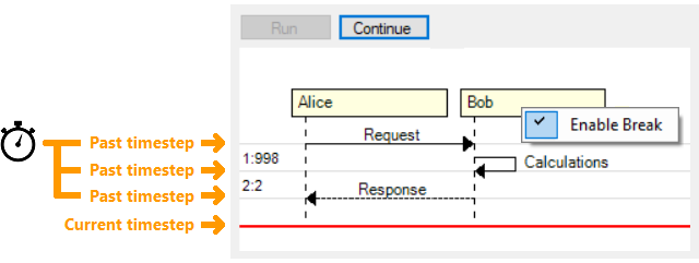
The implementation details of the breakpoint functionality is as follows:
- Whenever a
sequence.Tick()method is called, the underlyingSequenceobject calls its registeredOnEnterBreak()handler. This enables its parent form for tasks such as enabling itscontinueButton. - The sequence stays in wait state with this method:
private void ResponsiveWait()
{
    this.wait = true;

    for (;;)
    {
        if (!this.wait)
            break;

        if (this.exit)
            break;

        System.Windows.Forms.Application.DoEvents();
            System.Threading.Thread.Sleep(200);
    }
}
The Application.DoEvent() enables seizing execution flow without blocking itself or the application it resides in. The use of Application.DoEvents() is discouraged in favor of other techniques such as threads. But for this project's needs (such as minimal interference with the debugged application), I found it to be the most suitable method.
- When the user clicks the
continueButton,sequence.Continue()method is called and wait state ends. - The sequence class calls the registered
OnExitBreak()event handler. This enables its parent form for tasks such as disabling itscontinueButton, as execution resumes until the next break.
Rendition of Elements
The visual rendition of elements take place in SequenceDiagramControl class. Each UML element has a method and a reference point variable named p0.
API Reference


The Sequence class is the base object of the data model of the SequenceDiagramControl. All information about the sequence is stored in this class. It has collections of available participants, activations, messages and boxes.
Boxes are optional elements for grouping related participants.
Participants own a collection of activations, and each activation has a collection of name/value pairs called tags. Participants communicate with each via Messages.
Sequence
The Sequence class encapsulates the entire data within the sequence. It focuses on time sequencing or time ordering of messages between participants and the order in which messages are sent. The emphasis in the sequence is what happens first, second, and so on.
API Usage
sequence.Clear();
Clears the current state and all members of the sequence. The sequence returns to its initial state.
sequence.Tick();
The focus of the sequence diagram is to visualize a system's change and the communication of the elements over time. Whereas the x-axis displays the members of sequence (called participants), y-axis represents time.
In the SequenceDiagramControl model, the timeticks are represented as discrete values. Whenever a time tick occurs, the sequence advances to the next timestep value. The time tick is the point where a break occurs in which the user can respond to.
Participants
Participants are representatives or objects that take part in the sequence. They are usually placed across the top of the diagram. The participant is typically represented as a rectangle, and its name is placed inside the box. Per the UML specification, this name can be underlined meaning the participant represents a specific instance of a class in a sequence diagram. Additional information such as UML stereotypes can be included within the participant rectangle as well.
Lifeline of the participant is displayed as a vertical dashed line beginning from the bottom of the participant. They represent the life and interactions of the participant over time.

Participant foo1 = sequence.Participants.Create("Foo1", type: EParticipantType.Actor);
Participant foo2 = sequence.Participants.Create("Foo2", type: EParticipantType.Boundary);
Participant foo3 = sequence.Participants.Create("Foo3", type: EParticipantType.Control);
Participant foo4 = sequence.Participants.Create("Foo4", type: EParticipantType.Entity);
Participant foo5 = sequence.Participants.Create("Foo5", type: EParticipantType.Database);
Participant foo6 = sequence.Participants.Create("Foo6", type: EParticipantType.Collections);
sequence.Messages.Add("To boundary", foo1, foo2);
sequence.Tick();

sequence.Messages.Add("To control", foo1, foo3);
sequence.Tick();

sequence.Messages.Add("To entity", foo1, foo4);
sequence.Tick();

sequence.Messages.Add("To database", foo1, foo5);
sequence.Tick();

sequence.Messages.Add("To collections", foo1, foo6);
sequence.Tick();
API Usage
Participant participant = sequence.Participants.Create(string name, bool underlined = false,
Color? color = null, Color? textColor = null, EParticipantType? type = null, Box box = null,
bool createNow = false);
It creates a new participant and places it within the sequence. The call fails if the sequence already has a participant with the specified name.
name: Name of the participant.underlined: Whether the name of the participant will be displayed as underlined text. Underlined text in UML represents a specific instance of a class.color: Background color of the participant.textColor: Text color of the participant.type: Type of participant. It affects how the participant is displayed (Box, Boundary, Control, Entity, Database, Collection).box: The box which participant belongs to. This value may benull.createNow: This value is usually omitted, resulting in the participant being placed at the top of the diagram. Setting this value emphasizes that the participant is being created and its lifetime starts at the current timestep.
Participant participant = sequence.Participants.CreateOrGet
(string name, bool underlined = false, Color? color = null, Color? textColor = null,
EParticipantType? type = null, Box box = null, bool createNow = false);
If a participant with the given name exists, it returns it.
If a participant with the given name does not exist, it creates a new participant, places it within the sequence, and returns it.
name: Name of the participant.underlined: Whether the name of the participant will be displayed as underlined text. Underlined text in UML diagrams represents a specific instance of a class.color: Background color of the participant.textColor: Text color of the participant.type: Type of participant. It affects how the participant is displayed (Box, Boundary, Control, Entity, Database, Collection).box: The box which participant belongs to. This value may benull.createNow: Omitting this value, resulting the participant to be placed at the top of the diagram. Setting this value emphasizes that the participant is being created and its lifetime starts at the current timestep.
Participant participant = sequence.Participants[name];
It returns the participant with the given name. The call fails if a participant with the given name does not exist.
name: Name of the participant.
participant.Destroy();
Ends the current activation of the participant.
Messages
Messages represent the information transmitted between two participants. It is possible that a participant can send a message to itself. Messages can be synchronous or asynchronous, they may reflect the start and execution of an operation or the sending and reception of a signal.
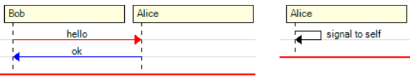
Participant bob = sequence.Participants.Create("Bob");
Participant alice = sequence.Participants.Create("Alice");
sequence.Messages.Add("hello", bob, alice, color: Color.Red);
sequence.Tick();

sequence.Messages.Add("ok", alice, bob, color: Color.Blue);
sequence.Tick();
Participant alice = sequence.Participants.Create("Alice");
sequence.Messages.Add("signal to self", alice);
sequence.Tick();
API Usage
Message message = sequence.Messages.Add(string name, Participant from,
Participant to, Color? color = null, DashStyle? dashStyle = null);
Creates a new message between a source and a destination participant.
name: Name of the message.from: The source participant of the message.to: The target participant of the message.color: The color the message is rendered.arrowHead: Arrow head of the message. Different arrow heads represent different types of messages.dashStyle: Dash style of the message line. Different dash styles represent different types of messages.
Message message = sequence.Messages.Add(string name, Participant self,
Color? color = null, DashStyle? dashStyle = null);
Creates a new self-message. The participant sends a message to itself.
name: Name of the message.self: The owner participant of the message.color: The color the message is rendered.arrowHead: Arrow head of the message. Different arrow heads represent different types of messages.dashStyle: Dash style of the message line. Different dash styles represent different types of messages.
Activations
Activations (also called Focus of control elements/Execution occurrences) are the period during which a participant is performing an operation. The time an object is busy executing a process or waiting for a reply is represented as a rectangle placed vertically on its lifeline. The top and the bottom of the rectangle are aligned with the initiation and the completion time respectively. Activations can be recursive.

Participant user = this.sequence.Participants.Create("User");
Participant a = this.sequence.Participants.Create("A");
Participant b = this.sequence.Participants.Create("B");
sequence.Messages.Add("DoWork", user, a);
a.Activate(color: Color.FromArgb(0xff, 0xbb, 0xbb));
sequence.Tick();

sequence.Messages.Add("Internal call", a);
a.Activate(color: Color.DarkSalmon);
sequence.Tick();

sequence.Messages.Add("<< createRequest >>", a, b);
b.Activate();
sequence.Tick();

sequence.Messages.Add("RequestCreated", b, a, dashStyle: DashStyle.Dash);
b.Deactivate();
a.Deactivate();
sequence.Tick();

sequence.Messages.Add("Done", a, user);
a.Deactivate();
sequence.Tick();
API Usage
participant.Activate(string name = null, Color? color = null);
Initiates an activation for a participant. The activations can be recursive.
name: Name of the activation.color: Background color of the activation.
participant.Deactive();
Deactivates the current activation of the participant.
Boxes
Boxes help organize a sequence diagram. Interrelated participants can be grouped within a box.

Box box = sequence.Boxes.Create("Internal Service");
box.Color = Color.LightBlue;
Participant bob = sequence.Participants.Create("bob", box: box);
Participant alice = sequence.Participants.Create("alice", box: box);
Participant other = sequence.Participants.Create("other");
sequence.Messages.Add("hello", bob, alice);
sequence.Tick();

sequence.Messages.Add("hello", alice, other);
sequence.Tick();
API Usage
Box box = sequence.Boxes.Create(string name, Color? color = null);
It creates a new box and places it within the sequence. The call fails if the sequence already has a box with the specified name.
name: Name of box.color: Background color of the box.
Box box = sequence.Boxes.CreateOrGet(string name, Color? color = null);
If a participant with the given name exists, it returns it.
If a participant with the given name does not exist, it creates a new participant, places it within the sequence, and returns it.
name: Name of box.color: Background color of the box.
Box box = sequence.Boxes[name];
It returns the box with the given name. The call fails if a box with the given name does not exist.
name: Name of the participant.
SequenceDiagramControl+AOP Library=A Debugger

SequenceDiagramDebugger is not a part of the SequenceDiagramControl. Rather, it is an extension for demonstrating a concrete, real-life use of the SequenceDiagramControl. In addition to this, there is a persistent criticism for existing AOP (Aspect Oriented Programming) samples is that nearly all of them involve either logging or access control of method calls. In this case, AOP is used for an alternative need: execution visualization.
The debugger sample serves as a proof of concept and has limitations such as supporting applications using a single thread only.
AOP enables intercepting methods of an application. These intercepted method calls are then visualized by the SequenceDiagramControl. With the control's additional built-in break functionality, this enables debugging an application's execution flow.
The mapping is between the application and sequence diagram elements is implemented as follows:
- Application -> Sequence
- Application class -> Participant
- Class method duration -> Activation
- Method call -> Message
An important objective is to enable debugging with minimal change to the host application. This is accomplished by adding a single line of code to the debugged application so that our tool integrates with it:
public MainForm()
{
    InitializeComponent();

    SequenceDiagramDebugger.Init(this, "TestApp.");
}
SequenceDiagramDebugger.Init(this, "TestApp"); serves two purposes:
- It weaves all methods of the debugged application in the "
TestApp" namespace. - It opens our
DebuggerForm, which contains aSequenceDiagramControl.
During execution, the AOP library informs us of every relevant occurrence of method entries and exits via advisors. These intercepted method entries and exits are then visualized in our SequenceDiagramControl based SequenceDiagramDebugger.
In the example, you click the 'Calculate' button of the TestApp once, and then the 'Continue' of the DebuggerForm until the end of the execution.

Points of Interest
Sequence Diagram Features Not Implemented
Some parts of the UML sequence diagram specification (such as the elements for representing loops, branches, and alternative execution flows) are meaningful only when the diagram is used for documenting the flow of a process. These features are omitted in the SequenceDiagramControl, as the control's focus is the dynamic visualization of what has already taken place, not what may be.
PlantUML
PlantUML is an open-source tool that aids in creating various types of UML and non-UML diagrams from text files conforming to its diagram definition syntaxes. You specify your UML diagram definition in the tool's text format and unlike SequenceDiagramControl, it creates a static image representation of the diagram. It has support for sequence, use-case, class, activity, component, state, object, deployment, and timing UML diagrams, as well as numerous non-UML ones.
I have long been using PlantUML tool for technical documentation, and I have been impressed by its easy to use terminology. So one of my design objectives has been to follow PlantUML's naming of elements as closely as possible, and compare PlantUML's and SequenceDiagramControl's renditions of the same sequence. All features samples I have provided have a corresponding one in the PlantUml tool sequence diagram creation page.
In this section, I provide the PlantUML text definition equivalents and their outputs of the two features samples I have described at the beginning of the article, so you can compare their similarities and differences:
The PlantUML text definition equivalent of the first feature sample:
@startuml
Alice -> Bob: Authentication Request
Bob --> Alice: Authentication Response

Alice -> Bob: Another authentication Request
Alice <-- Bob: Another authentication Response
@enduml
When you feed this text to the PlantUML parser, you get the following (static) sequence diagram:

And this is the PlantUML equivalent of the second features sample I have described above.
@startuml
participant User

User -> A: DoWork
activate A

A -> B: << createRequest >>
activate B

B -> C: DoWork
activate C
C --> B: WorkDone
destroy C

B --> A: RequestCreated
deactivate B

A -> User: Done
deactivate A

@enduml
Its PlantUML output is:

NConcern and CNeptune
NConcern and CNeptune are the AOP libraries that have been used for intercepting method calls of external applications in the SequenceDiagramDebugger sample. These captured method calls are visualized in the SequenceDiagramControl. The libraries are robust and well-designed: I was able to integrate them with minimum effort.
NConcern provides the functionality and API for AOP (such as the advisors).
CNeptune is the mono.cecil based utility for rewriting .NET assemblies to make them injectable.
History
- Version 1.0 (10th February, 2020): Initial release
Acknowledgement
I would like to express my special thanks of gratitude to Asst. Prof. Yunus Emre Selcuk who has given me the opportunity to work on the project which this control is a part of. Without his contribution, it would not have been possible to bring together what is here.