
Monitor & Store Temperature Stats For Home Zones With Arduino
Build one or more of these devices so you can monitor how temperature fluctuates over time in your home.
- Download source code (v001) - 283 B
- Download source code (v002) - 502 B
- Download source code (v003) - 562 B
- Download source code (v004) - 762 B
Introduction
Temperature can be quite subjective since for different reasons, each individual may experience it in relation to their own situation (drinking a hot or cold beverage, coming inside after taking a run in hot weather, coming inside after being out in cold weather, etc).
Background
In general, home thermostats are only installed in one location and only measure the temperature in that one location. However, another room or zone in the home may create a completely different temperature experience for the occupants. I thought it might be nice to build a simple device which:
- displays the current temperature
- stores time and temperature on an SD card for easy import into a spreadsheet so we can graph temperature over time
Attempt to Turn Subjective Feelings into Data
All this data could really help us turn the subjective idea that "it feels cold/hot in here" into real data that may allow us to know whether that is a "feeling" or a reality.
Here's a snapshot of everything you need for this project.

Parts List
It's always best to have a list of the parts and approximate prices so you can easily determine where to get the parts and how much the project is going to cost.
- Arduino Uno - I use the Elegoo clone (https://amzn.to/2JOoiIp) about $11 USD
- I2C LCD - (https://amzn.to/2NBWl8S) I showed you how to use this in my other article (Discovering What Your Code Is Doing Using a 20x4 LCD With Your Nano[^]) about $10 USD
- Main Temperature component - I'm using one from a Seeed kit. http://wiki.seeedstudio.com/Grove-Temperature_Sensor_V1.2/^ about $2.80 USD
- (Micro) SD Card Reader/Writer - This device also uses I2C (https://amzn.to/2A5nxLd) $8.99 for 5 of them
- Breadboard - I use these (https://amzn.to/2uVHteA) about $8.50 USD for 3
- (Micro) SD Card of any size - mine's 16GB because they were the smallest/cheapest I could find. (https://amzn.to/2LyLQpp) About $7.60 USD
- SD Card adapter - for carrying your files to your computer to import them into a spreadsheet for analysis
Do Things in Steps
A couple of guidelines I use when building out a project are:
- Do the easiest parts first
- Add layers of functionality
For me, this means getting the I2C LCD working. There are three reasons for this:
- The 12C LCD is easy to set up.
- It allows me to test a basic Arduino sketch
- I can use the LCD for output as I build the project - as a debugging tool if I need it.
Hook Up & Test the I2C LCD
Here's the circuit wired up on a breadboard.
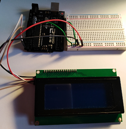
It's not extremely clear which pins on the I2C LCD are connected to the pins on the Arduino Uno so a schematic view can be far more clear about how things are connected.

Now you can plainly see that the VCC and GND pins are connected from Uno to LCD and the SDA pin on the LCD is connected to pin A4 (Analog 4) and the SCL pin on the LCD is connected to A5.
Here's the first sketch we will use to insure the LCD is working properly and that your circuit is setup properly.
#include <LiquidCrystal_I2C.h>

LiquidCrystal_I2C lcd(0x3F, 20, 4);

void setup() {

  lcd.begin();
  lcd.setCursor(2,0);
  lcd.print("Hello, LCD!");
}

void loop() {

}
You can see that this first simple sketch doesn't even contain any code in the loop() method. All the sketch does is print "Hello, LCD!" to the screen. But, this lets us know that we are ready to print any data that we receive.
All you have to do is upload the sketch from the Arduino IDE and you'll get some output on the screen.
Here's a snapshot of it running.

Get the Code and Try It
You can get the code (TempSensor_v001.zip) at the top of this article and try it out yourself.
Adding the Thermistor
We are ready to add the temperature reading module (thermistor) to our circuit.

It's a very simple component to use. In the previous picture, you can see that about in the middle of the component, there are four pins (horizontal) sticking out from the white plastic piece at the bottom. They are marked (from bottom to top):
- SIG (Signal)
- NC (Not Connected / unused)
- VCC (input Voltage)
- GND (Ground)
Connector Bundle
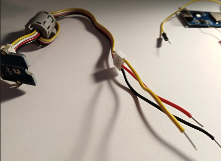
These Seeed modules are set up to be easy to use so they also provide a connector bundle that allows you to snap on all four wires by plugging them into the plastic receptacle shown on the left side of the component in the previous picture.
Once you plug that bundle in, it will look like the following:

Seeed also insures the color coding is set nicely so the red is always VCC, Black is GND and the yellow and white are generally data wires of some type. In this case, the thermistor only needs on more wire so the NC (Not Connected) aligns with the white wire and we will not connect anything to that wire.
Connecting the Bundle to the Breadboard
The other end of the bundle has the same connector and each of the wires terminate in a female connector as shown.

I will just strip some of my hobby wire and push the ends into the connector. Then I will connect those wires to the breadboard. You can see what the connector looks like after I've pushed wires into it in the following picture:
Now I connect the red to the VCC (breadboard power rail) and the black wire to ground (breadboard ground rail) and the yellow to a column on the breadboard. After that, I connect the breadboard column with the yellow wire connected to the Arduino Uno A0 pin (Analog 0).

Again, that isn't exactly clear about how things are connected so here is a schematic of the entire circuit so you can see exactly what is connected.

That's all there is to the circuit. Now we just need to add some code that will read the value from the powered up temperature sensor.
Code to Read Current Temperature
I got the code from the sample at the product site: http://wiki.seeedstudio.com/Grove-Temperature_Sensor_V1.2/#software^
Two Differences in Code
However, I altered the original code in two ways:
- Their code displays on the serial monitor (requires your Arduino to be connected to your computer), but of course ours displays the value on the LCD.
- The original displays the value in Celsius, but I've added a line to convert to Fahrenheit.
Get the Code
Here's the entire code listing. You can get the code by downloading TempSensor_v002.zip.
#include <LiquidCrystal_I2C.h>
#include <math.h>

const int B = 4275;               // B value of the thermistor
const int R0 = 100000;            // R0 = 100k
const int pinTempSensor = A0;     // Grove - Temperature Sensor connect to A0

LiquidCrystal_I2C lcd(0x3F, 20, 4);

void setup() {

  lcd.begin();
  lcd.setCursor(2,0);
  lcd.print("Hello, LCD!");
}

void loop() {
  int a = analogRead(pinTempSensor);

  float R = 1023.0/a-1.0;
  R = R0*R;
  float temperature = 1.0/(log(R/R0)/B+1/298.15)-273.15; // convert to temperature
                                                         // via datasheet
  temperature = (temperature * 1.8) + 32;                // convert temp to Fahrenheit
  lcd.setCursor(2,1);
  lcd.print(temperature);
}
Every time the program goes through the loop, it will get the current value of the temperature sensor and display it on the LCD.
The Sig (data pin) of the temperature sensor is connected to A0 of the Arduino.
The Basics of How the Temperature Sensor Measures Ambient Temperature
The first thing the code does is read the analog value from pin A0 which is a value in the range of 0-1023. This value is stored in the a variable.
The Analog pins of the Arduino (and underlying Atmega328 MCU) can read voltages which are split into a range of 1024 values. As the ambient temperature around the sensor goes down, the sensor's resistance will increase. This in turn will lower the value of the voltage on the A0 pin which lowers the value in the range (0-1024).
The math of the following line allows us to know the temperature (in Celsius) in relation to the resistance that is occurring within the sensor:
float temperature = 1.0/(log(R/R0)/B+1/298.15)-273.15;
Once we have the Celsius temperature, it is an easy matter of applying the conversion formula to convert it to Fahrenheit.
After that, we simply display the value on the LCD.

But, now we need to add a way to store the temperature values we obtain over time. SD Card Reader/Writers are inexpensive and allow us to carry the data to computer for more analysis so we'll implement one of those here.
SD Card Reader/Writer
I've added a close up of the SD Card Reader/Writer front side and back side below. It's very simple to use because it uses I2C also.

I've already loaded the 16GB SD card into the spring loaded card holder (on the left side of the reader/writer). You can see a bit of the card sticking out to the left.

You can see that the pins are marked nicely for our use.
SD Card Reader/Writer Uses SPI (Serial Peripheral Interface)
Whenever you see that a component uses MOSI, MISO, SCK, and CS (also sometimes marked SS) then you know that it uses SPI (Serial Peripheral Interface) for communication of data.
The SCK is the Serial Clock which sets the data pulses (speed) that the master will send the data. It's basically a way to insure the Master and Slave device understand the timing that the data will be sent.
The CS (Chip Select) or SS (Slave Select) is the pin used to determine which Slave is going to receive the data.
This interface allows multiple devices connected to these four pins to communicate with the master. This saves data pins on your Arduino but allows you to connect multiple devices.
You can read much more about SPI at https://www.arduino.cc/en/reference/SPI^.
We will connect the four pins to our Arduino pins as follows:
- MOSI (Master Out/Slave In) => D11
- MISO (Master In/Slave Out) => D12
- SCK (Serial Clock) => D13
- CS (Chip Select) => D10
Updated Schematic
Here's an updated schematic so you can more easily tell how everything is connected.
I moved things around a bit (from the previous schematic) just so lines wouldn't overlap as much with the newly added component.

This component's pins make it easily used with a breadboard. I just push it into the board so each pin gets its own column on the breadboard.

Now, it's just a simple matter of making the connections with our jumper wires.
Then we can add some code to test writing to the SD card.
We will add two new includes which will provide us with functions to initialize and use the SD Card reader/writer.
#include <SPI.h>
#include <SD.h>
Next we'll declare a couple of variables we'll use:
File TempData;
const int SD_CS = 10;
The first line declares the File handle to the file that we'll be writing to.
The second line creates a variable for the CS pin of the SD card reader and ties it to the digital pin 10 of the Arduino. We do that so we can then initialize the SD object that we'll use to write to the file.
We'll add the following code to the setup() function:
if (SD.begin(SD_CS)) {
    lcd.setCursor(2,2);
    lcd.print("SD card init");
  }
This will print "SD card init" to the LCD only if the SD card reader is wired up properly.
Get Code and Try It : TempSensor_v003.zip
Get the TempSensor_v003.zip at the top of this article and try it out.
If everything is good to continue, then you'll see something like the following:

If that worked, then you know you have things wired up properly and you're ready to continue.
Writing Temperature Data To A File
Let's add the code that writes to a file.
I'm going to add that code to a function and then have the loop() method call the function each time. I've named the function writeToSD.
void writeToSD(float temperature){
    TempData = SD.open("temps.csv", FILE_WRITE);
    if (TempData) {
      lcd.setCursor(2,2);
      lcd.print("file WRITE success");
      TempData.print(millis());
      TempData.print(",");
      TempData.println(temperature);
      TempData.close();
    }
    else{
      lcd.setCursor(2,3);
      lcd.print("file WRITE fail    ");
    }
}
There's not much code to write the file to the SD card. It's very simple and the methods are provided by the Arduinio SD library that we included at the top of the source file.
Here's what the data looks like when you open it up in a text editor. It's just simple comma separated values:
- column 1 is the number of milliseconds since the program started
- column 2 is the temperature at that time

This was gathering data every 500ms so the temperature hadn't changed much. Here are some more details about dealing with files.
Opening / Creating A File For Writing
The first thing we need to do is set the File Handle to point to the actual file we want to write to. We can do that by calling the SD.open() method. You can see that I've provided the string name "temps.csv" as the first parameter and the predefined value FILE_WRITE to indicate that I want to open the file for writing.
File Is Created
If the file exists, it will be opened for writing (appending to the end). If the file does not exist, then it will create the file and then open it for writing.
File Open Success
If the file is successfully opened (and created, if necessary), the TempData File handle will not be null. That means we can simply code:
if (TempData)
If the file handle is not null, then we can write to it using the print() and println() methods. The only difference between the two methods is that println() adds a CrLf (Carriage-Return / Line-Feed) to the end of the line after it writes the data to the file.
Importance of Closing File After Writing
Finally, after writing the data to the file it is very important to call the close() method to insure the bytes are flushed from memory and written to the disk file (file on SD).
That's all there is to it. The rest of the code just gives us some output on the LCD screen in case things fail and to provide us with a status about what is happening.
Importance of FileNames With 8.3
When I first set up the code, I had the following line to open the file:
TempData = SD.open("temperature.csv", FILE_WRITE)
I didn't know that line was the problem but when I went to write to the file, it always failed. I couldn't figure it out for a bit, but then I guessed that maybe this file system only allows 8.3 file names. I looked it up and that was the problem. Since I'd provided a longer file name the open() call was failing and TempData was null and then the write was failing. That's not so easy to determine though because we don't have an Arduino debugger.
The next thing we need to solve is writing the data at a specific interval. We don't want to write data to the SD card every time through the loop() because the data wouldn't be useful.
Only Write Data at Time Intervals
We only want to write data every X seconds to limit the amount of data we write to the SD card. The millis() function returns the number of milliseconds since the sketch started running on the Arduino.
To handle this, we could call delay(ms) each time through the loop(). However, that pauses the entire sketch and it really isn't effective. Instead, I want to make the sketch only call the writeToSD() function every X seconds.
I'm going to have it write the data every minute so at the top I will initialize two variables we will use to do this:
const long SLEEP_TIME = 60000;  // write to card every minute
long multiplier = 0;
The SLEEP_TIME variable is simply a constant so we can easily change the value in one place. That's the amount of time that will be in between each call to writeToSD().
The next variable which I call multiplier is simply a counter which starts at zero and will help us only make the call to writeToSD() every SLEEP_TIME seconds. With those two variables in place, we will be able to use the following code to insure writeToSD() only occurs every interval.
if (millis() > (multiplier * SLEEP_TIME)){
    writeToSD(temperature);
    multiplier++;
}
The first time through the loop, the multiplier will be 0 and millis() will be something greater than zero which means the sketch will immediately write the first temperature it reads to the SD card. It will then increment the multiplier.
The next time through the loop, millis() will be less than multiplier * SLEEP_TIME (1 * 60000) so it will not write again until millis() has been running for at least one minute. It will continue to do this every minute since the multiplier will be incremented each time.
Final Code : Get TempSensor_v004.zip
Get the code and try it out. Here, it is running on my desk.

Take It Even Further
Now if you want, you can take this even further by making the device more portable. I won't cover the additional details here -- to keep this project shorter -- but you could do some extra work and make it run from batteries.
You could also add a real-time clock -- which Atmega328 chips do not have available -- so you could write clock times to your file so you can more easily track the temperature against time. You can buy real-time clocks as a component you hook up on to your Arduino (see Amazon link: https://amzn.to/2OqmR6v^) That component uses SPI just like the SD card so you'll already know how to hook it up.
Topics Touched Upon
Now you know how easy it is to read data from a temperature sensor. You also learned a bit about:
- Arduino's File Reading / Writing Library and associated challenges
- SPI - Serial Peripheral Interface used by the SD card (MOSI, MISO, CS, and SCK). Whenever you see those four connections used, you'll know the device is using SPI.
Salient Points To Keep In Mind
- The SD Card reader doesn't have any LEDs to indicate when it is powered or reading or writing and that makes it a bit difficult to determine what is wrong if it isn't writing. You'll need to use LCD
print()statements to debug it if it fails. Also, keep a close eye on how you have it wired up. - Make sure your temperature sensor isn't too close to the running Arduino board which puts off some heat and may alter your readings.
- If you want more data, simply alter the
SLEEP_TIMEvariable so it is a smaller interval. For example, change it to 5000ms and the sketch will write data every 5 seconds. - SD card formatting can have odd effects on your SD card. If you're getting odd effects of writing to your card, check here^.
- It was also interesting that I needed to make the
multiplierandSLEEP_TIMEvariableslongs because I was multiplying them and the product ended up being a number larger than anintand the program would stop when thatintvalue was exceeded, even though I wasn't actually storing them in anintvariable. Instead, anintsize of temp memory was being allocated automatically for the product and when it couldn't hold that value, the statement (if (millis() > (multiplier * SLEEP_TIME))) would fail. It makes sense, but it caught me off guard.
History
- 28th July, 2018: First publication