
Connecting an Arduino to a Breadboard to light up LEDs using Tinkercad
5.00/5 (6 votes)
This article will guide you through creating a simulated Arduino project connected to a breadboard using Tinkercad
Getting started with Arduino and want to try an easy project? This project takes about 45 minutes, is fun to do, and it even has blinking lights!
There are two versions of this article:
- this article which uses a browser based Arduino Simulator
- a separate one where you connect a real world Arduino to a breadboard then control LEDs (https://www.codeproject.com/Articles/1247040/Connecting-an-Arduino-to-a-Breadboard-to-light-u)
It's actually interesting to do both of the projects if you have time, same application, one real world and one virtual.
Let's get started.
Introduction
This article will get you up and running with a simple project involving an Arduino simulator, a breadboard, and a handful of LEDs.
The project guides you through the steps required to make an 8-bit binary counter. Once it's working, you can easily experiment with other sequences and effects. It's a great first project for Arduino, or if you haven't used your Arduino it's a great way to get back into it.
Getting started
To get started with the simulator, go to https://www.tinkercad.com and create a free account. Once you’ve done this, you’ll to taken to the Tinkercad dashboard. In the menu on the left side of the screen, click ‘Circuits’. Now, on the right side of the screen, click the ‘Create new Circuit’ button to get started. When the circuit design screen loads, click the Components drop-down box, and choose 'All'. You’re now ready to build a binary counter! Just follow the steps below to get started.
- In the parts list at the right of the screen, scroll down until you the Breadboards and Microcontrollers. Click and drag an Arduino and a small breadboard onto the workspace. Place the breadboard above the Arduino.

- Hover the mouse cursor over the GND pin on the top of the Arduino. When the GND pin is highlighted in red, click the mouse to begin connecting a wire.

- Move the mouse to the bottom hole of row 1 on the breadboard, and when the hole is highlighted in red, click to connect the wire. On the simulated breadboard, notice that there are 30 rows of pins. Each row has 10 pins, labelled from a to j. You just connected a wire to pin 1a.

- Sometimes, it's helpful the bend wires before connecting them. This prevents visual clutter and can help make your circuits easier to understand. Let's practice this now. Click on the wire you just added to select it.

- Press the delete key to remove the wire.
- s in step 2, move the mouse to the GND pin on top of the Arduino. Click, move the mouse to a point about halfway between the Arduino and breadboard, and then click again. While you're drawing a wire, clicking the mouse when you aren't hovering over a connection point adds a bend in the wire.

- Move the mouse left until it is directly below row 1 on the breadboard, then click again. Now, move the mouse to pin a of row 1. When you see the pin highlighted in red, click again. This will connect the wire.

- Since this wire is connected to ground (-) click on the drop down box to change its color to black. While the color of the wire doesn't affect the circuit, black wires are usually used to - and red wires are used to connect to +. Following these conventions makes our circuit easier to understand when we look at it.

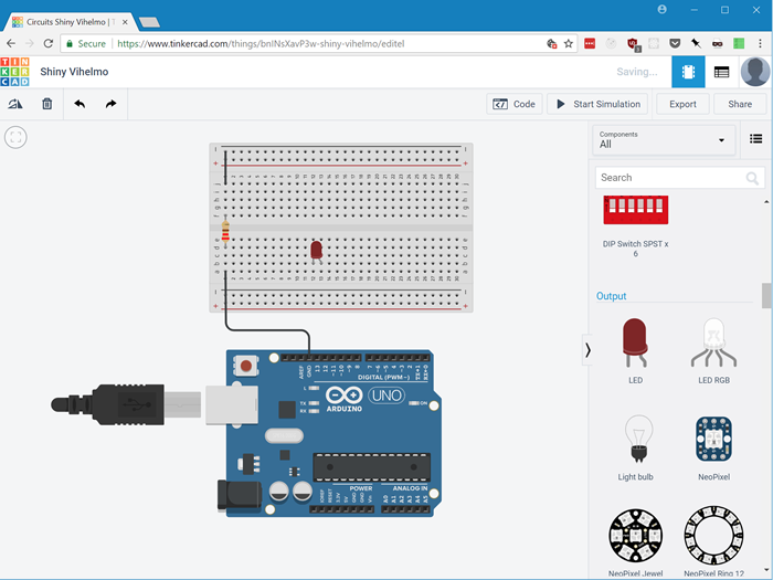
- In the parts list, find the Resistor. Click and drag a resistor onto the breadboard so that it is connected to pins 1d and 1f.

- In the box at top right, change the resistor's resistance to 220Ω. Make sure you click the drop-down to change the units from kΩ to Ω.

- Add a black wire connecting pin 1j to the negative power rail on the top of the breadboard.

- Find the LED in the parts list, and drag one onto the breadboard so it is connected to pins 12b and 13b.
- Add 7 more LEDs to the right of the first one. Make sure they're all in column b, and don't leave any spaces between them.
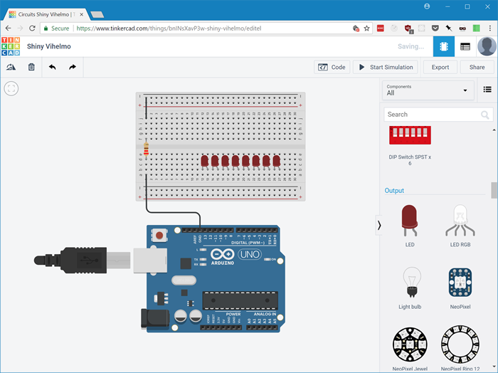
- Connect black wires from the top power rail to pins 12e, 14e, 16e, 18e, 20e, 22e, 24e, and 26e. This connects this negative side of the circuit to each LED's cathode. In the simulator, each LED's cathode pin is straight, and the anode pin is bent. It's important to get this right, because diodes - including LEDs - only allow current to flow in one direction.

- Now, it's time to connect the Arduino's output pins to the anodes of the LEDs on the breadboard. Add a wire from pin 5 on the Arduino to pin 27a on the breadboard, which connects to the anode of the rightmost LED. Next, connect pin 6 on the Arduino to pin 25a on the breadboard. Continue in this pattern until you finish up by connecting pin 12 on the Arduino to pin 13a on the breadboard.


- Connect a wire from analog pin 0 on the Arduino to an unused row on the breadboard. In the example below, we’ve connected to wire to breadboard port 30a.
Your binary counter circuit is now ready to go! You’re ready to move on to writing the Arduino code that will make the counter work.

And we’re done! We’re ready to move on and write the code that will make the counter work.
Adding the code
Note that this part is exactly the same as in the companion article "Connecting an Arduino to a Breadboard to light up LEDs"
It’s time to write the code to make our binary counter work. In the Arduino world, programs that are written and uploaded to an Arduino device are called ‘sketches’. A sketch can contain multiple files, as long as they’re all saved in the same directory. Since this is a very simple project, we’re going to put all our code in a single file.
When using Tinkercad you can enter code by clicking on the ‘Code’ button near the top of the screen. At first, you won’t see anywhere to enter your code. In the code window, you’ll see a drop down box that lets you choose between ‘Blocks’, ‘Blocks + Text’, and ‘Text’. Choose ‘Text’, and you’ll be presented with an editor window where you can write code. Your code will be automatically saved as you enter it. Once code is entered on Tinkercad, it is able to run on the simulated Arduino immediately. No upload step is required. When you’re ready to run your code, click on the ‘Start Simulation’ button and your code will start running immediately.
Arduino sketches are written in C++. The Arduino IDE supports C++11, so you can use all of its new features if you’d like. We’re going to stick to C++98, since that’s what the Tinkercad Arduino supports. That way, we end up with code that’ll work no matter where you want to run it. Note that the Arduino environment doesn’t include the C++ Standard Library. So you won’t be able to use things like vectors or C++ strings. There’s an implementation of the C++ Standard Library for Arduino available on GitHub, but we won’t need it for this project.
To begin, we’ll cover a few functions that we’ll need to use to get the Arduino to light up our LEDs. These functions are all available globally. You won’t need to import anything to use them.
The first function we’ll need to use is pinMode. This function is used to tell the Arduino whether a pin will be used for input or output. It is used like this:
pinMode(10, OUTPUT);
This would, as expected, set pin 10 to output mode. The second parameter can be set to either INPUT or OUTPUT. These are both constants that are available globally in any Arduino sketch.
Next up is digitalWrite. This function lets us turn a specific output pin on or off. To turn a pins off or on, we can use two more global constants: LOW and HIGH. These constants aren’t anything special. If you look them up in the Arduino source code, you’ll see that LOW is 0 and HIGH is 1. So, for example, to turn pin 10 off you could write either of the following:
digitalWrite(10, LOW);

digitalWrite(10, 0)
and to turn pin 10 on, you could use either of:
digitalWrite(10, HIGH);

digitalWrite(10, 1)
Next is analogRead. As its name implies, analogRead is used to read an analog value from one of the Arduino’s analog pins.
The final function we’ll need is delay. This function does exactly what its name implies. It causes the Arduino to pause before executing any more code. It takes a single parameter: the number of milliseconds to pause for. So, to pause execution for 1 second, you’d write:
delay(1000);
The delay function will be important to our binary counter, because we’ll want to pause for a moment after each time we increment the encounter. Although the Arduino is small and not very powerful, it can still count from 0 to 255 so quickly that we wouldn’t even see the counter LEDs changing.
To enter your code, you’ll need to download the Arduino IDE if you are using physical Arduino hardware, or open the code view if you’re using Tinkercad. To do this, click on the ‘Code’ button, and in the drop-down choose ‘Text’ - it is set to ‘Blocks’ by default.
Now that we understand the Arduino functions we’ll need, let’s dive in to the code that will make our binary counter tick. To keep everything nice and organized, we’re going to wrap our counter in a class:
class BinaryCounter {
};
Next, let’s fill out our class with the variables and methods it will need to do its work:
class BinaryCounter {
  private:
    static const uint8_t digitCount = 8;
    const uint8_t pins[digitCount] = {12, 11, 10, 9, 8, 7, 6, 5};
    uint8_t count = 0;

    static const uint8_t showSingleValuePin = 0;
    uint8_t valuetoShow = 255;

  public:
    BinaryCounter();
    void increment();
    uint8_t* getBinaryDigits(uint8_t num);
    void clearLights();
};
Let’s take a quick look at the variables just added. Up first, we’ve got a count of the number of digits our binary counter will contain. We could easily just hardcode this number 8 if we wanted to, but storing it in one place makes it very easy to update our code if we want to change the number of digits our binary counter contains.
Next up, we have an array and contains the pin numbers each LED is connected to. We’ve listed them in left to right order. This will make things nice and easy later on when we want to iterate through the pins from left to right to turns LEDs on or off.
Next, we have a variable that will store the counter’s current value.
Why uint8_t, you might ask, instead of just int? On Arduino, an int takes up 16 bits of memory. As its name implies, uint8_t only takes up 8 bits. And since we’re using 8 LEDs, we only need 8 bits to represent any number we’re capable to displaying. Although it makes no difference in a small program like this one, it’s good to get in the habit of only using what you need. Arduinos only have 2KB of RAM, so it’s easy to use it all up very quickly.
Now it’s time to move on to the meat of our code. We’ll start by writing a constructor for the BinaryCounter class.
BinaryCounter::BinaryCounter() {
  //set all counter pins to output mode
  for(int i = 0; i < digitCount; i++) {
    pinMode(pins[i], OUTPUT);
  }
The constructor only does one thing: it iterates through the pins we’ll be using, and sets them to output mode.
Next, we need a method that takes a uint8_t, and returns an array of uint8_t. There’s just one catch: C and C++ won’t let you return an entire array. But we can easily make an array on the heap and return a pointer to its first element, so that’s what we’ll do. We’ll just have to remember to delete it when we’re done with it.
uint8_t* BinaryCounter::getBinaryDigits(uint8_t num) {

  // Make a byte array to hold all of the binary digits.
  uint8_t *digits = new uint8_t[digitCount];
  memset(digits, 0, digitCount * sizeof(uint8_t));

  uint8_t remaining = num;
  uint8_t currentPosition = digitCount-1;

  while(remaining > 0) {
    digits[currentPosition] = remaining % 2;
    remaining /= 2;
    currentPosition--;
  }

  return digits;
}
The first line of code creates a uint8_t array large enough to hold all of our digits, and the second line of code sets all elements of the array to 0.
Next, we go through the process of actually converting the integer to a binary number.
The math behind integer to binary conversion is relatively simple. We just take our number, and continually divide it by 2 until we’re left with 0. At every step, if the current number remaining is divisible by 2, then the step’s binary digit will be 0. If the current number is not divisible by two, the binary digit at that step is 1. For a more in-depth explanation, see this blog post. The best way to gain an understanding of integer to binary conversion is to do a few conversions by hand. Once you’ve done this, you’ll find the whole process much easier to understand.
Note that we’re walking through the digits array backward to set the values. The method we’re using to convert integers to binary gives us the digits in right-to-left order. By stepping through the array backwards, we’re ensuring that we set the correct values for each pin.
Once we’re done, we return the pointer to the beginning of the digits array.
Next, we’ll add code to increment the counter and turn on the LEDs that represent the current binary count:
void BinaryCounter::increment() {
  uint8_t* binaryDigits;

  if(analogRead(showSingleValuePin) > 500) {
    binaryDigits = getBinaryDigits(valuetoShow);
  }
  else {
    binaryDigits = getBinaryDigits(count);

    if(count == 255) {
      count = 0;
    } else {
      count++;
    }
  }

  for(int i = 0; i < digitCount; i++) {
      digitalWrite(pins[i], binaryDigits[i]);
  }

  delete binaryDigits;
  delay(500);
}
We start by checking to see if a wire is connected to analog pin 0 (set in showSingleValuePin). If so, we generate an 8 bit code from the value in valuetoShow. If no wire is connected, then we run the code that increments our counter.
If we’re running the counter, we start by calling getBinaryDigits to turn the current count into an array of binary digits.
Since the array we get back from getBinaryDigits contains the digits in left-to-right order, and our pins array contains the output pins in left-to-right order, we can use a simple for loop to step through both arrays and set each pin to its corresponding value the the binaryDigits array.
Since digitalWrite turns a pin off if passed a 0 as its second parameter, and turns a pin on if it receives a 1, the net result is that our LEDs display the current binary count: any digit that is a zero results in a turned off LED, and any digit that is a 1 results in a turned on LED.
After we loop through and turn the LEDs on and off, we delete the binaryDigits array since we’re done with it. It’s very important not to forget this step. If you do, your program will have a memory leak. The Arduino will run out of memory and lock up very quickly. This won’t damage the Arduino, but your counter will only work for a short time and then freeze.
Next, we check if the count has reached 255, since 255 is the largest number we can represent in binary with 8 LEDs. If we’ve reached 255, we reset the counter to 0. Otherwise, we increase the count by 1. You might notice that we could actually skip this check and just increment the counter. Since 255 is the largest value a uint8_t can hold, if we try to increment the count when it is already 255, it will just overflow to 0.
In cases like this, though, it’s best to be explicit. Relying on the uint8_t to overflow from 255 back to 0 would work, but doing so would make our code harder to understand. Even if you’re the only person who will ever look at the code, you might end up confusing yourself if you come back to the code after not seeing it for a few months.
Finally, we delay for 500 milliseconds. This causes the Arduino to pause for half a second before moving on to the next digit.
And that’s it for the BinaryCounter class. We’re almost done! We just need a few more lines of code to initializer our counter and make it count:
BinaryCounter *counter;

void setup()
{
  counter = new BinaryCounter();
}

void loop()
{
  counter->increment();
}
We start off by creating a global variable to store a pointer to a BinaryCounter. In general, global variables are something that developers try to avoid. The Arduino programming environment is a bit limited, though. Creating a global BinaryCounter is the only way to make it available to Arduino’s loop function.
Next, we see two functions: setup and loop. These are both part of the Arduino programming environment. The setup function runs once when the Arduino boots up and executes your program. The Arduino then runs the loop function continually.
The rest of our code is simple: in setup, we create a new instance of BinaryCounter. Then, every time loop runs, we call the counter’s increment function to set the LEDs and increment the counter.
And...that’s it! That’s all the code we need to make the binary counter work.
In Tinkercad, click the “Start Simulation” button.
Now, just kick back, relax, and watch your binary counter in action!
Complete code listing:
class BinaryCounter {
  private:
    static const uint8_t showSingleValuePin = 0;
    static const uint8_t digitCount = 8;
    const uint8_t pins[digitCount] = {12, 11, 10, 9, 8, 7, 6, 5};
    uint8_t count = 0;
    uint8_t valuetoShow = 255;

  public:
    BinaryCounter();
    void increment();
    uint8_t* getBinaryDigits(uint8_t num);
};


BinaryCounter::BinaryCounter() {
  //set LED all pins to output mode
  for(int i = 0; i < digitCount; i++) {
    pinMode(pins[i], OUTPUT);
  }
}


uint8_t* BinaryCounter::getBinaryDigits(uint8_t num) {
  // Make a byte array to hold all of the binary digits.
  uint8_t *digits = new uint8_t[digitCount];
  memset(digits, 0, digitCount * sizeof(uint8_t));

  uint8_t remaining = num;
  uint8_t currentPosition = digitCount-1;

  while(remaining > 0) {
    digits[currentPosition] = remaining % 2;
    remaining /= 2;
    currentPosition--;
  }

  return digits;
}

void BinaryCounter::increment() {

  uint8_t* binaryDigits;

  if(analogRead(showSingleValuePin) > 500) {
    binaryDigits = getBinaryDigits(valuetoShow );
  }
  else {
    binaryDigits = getBinaryDigits(count);

    if(count == 255) {
      count = 0;
    } else {
      count++;
    }
  }

  for(int i = 0; i < digitCount; i++) {
      digitalWrite(pins[i], binaryDigits[i]);
  }

  delete binaryDigits;
  delay(500);
}

BinaryCounter *counter;

void setup()
{
  counter = new BinaryCounter();
}

void loop()
{
  counter->increment();
}