
Practical Electronics For Makers (Part 3 of N)
Further investigation of switches (mercury, tilt, slider, magnetic) with circuits and our first automation circuit using an Infrared sensor
Background
I have been overwhelmed by the kind responses to the first two chapters of Practical Electronics For Makers. My original hope was that a community would form where ideas would be shared and this has happened. I'm especially thankful for the responses I've received from others who have many years of experience and who've set me right on a couple of issues which I've gone back and edited.
As you read this new chapter, keep in mind that I am an observer / experimenter who tries to ensure I have experiences and then tries to capture those experiences as a way of pointing others in directions that they can then launch from. These are things I find interesting and I want to know more about so I try some experiments. Often, I find that as I'm trying the one thing that I have to learn another thing so I can explain the first thing I was trying.
It's all very exciting but it is also very challenging. I find that I want to explain numerous things at one time and that as I'm writing, at times I suddenly understand the picture I want to take when I'm experimenting but then have to move from writing back to the picture taking / experiment and it breaks up the flow. Then when I go to take a "simple picture", I find that getting it set up and showing everything as I would like it to isn't easy or in many cases possible. Many of the challenges actually make me feel inadequate for the work and at times, I believe I will just give up. However, even if I gave up, I would still be experimenting and building and working with electronics and finding things that I would want to share and so the cycle would start all over again.
So, instead of giving up, I'm giving you these notes up front to tell you, I am an observer and a collector of interesting ideas. I will also do my very best to be an explainer of ideas and a documenter of the experiments, but I will fall short of my lofty goal of getting good pictures and writing great explanations and I apologize for that and hope you will stick with me and always find our discussions interesting.
~Roger
Chapter 3
You can read previous chapters here on CodeProject:
The Importance of Switches (Continued)
Here’s What You Need
- IR sensor (http://amzn.to/2zWGz2G)
- Tilt / Shake switches (http://amzn.to/2FPRAFx)
- Magnetic switch (http://amzn.to/2GpZiXa)
- Toggle switch (SPDT) http://amzn.to/2hYZfr1 or http://amzn.to/2hnIIzs
- Push button - momentary switch
- LEDs (http://amzn.to/2CwlufU)
- Multimeter (http://amzn.to/2CsC3JL or (http://amzn.to/2Exa7F5)
- Battery holders (http://amzn.to/2lUH4Um)
- Slide switch (http://amzn.to/2CQYs3y)
- Resistors 220, and 22 Ohm (http://amzn.to/2CuEECU)
- Wire (22 or 24 AWG) (http://amzn.to/2qwsp7i
- Wire strippers (http://amzn.to/2lXANY7 or http://amzn.to/2FfTKP2)
Here’s What We Will Observe Together
- See numerous switches
- Mercury
- Tilt / shake
- Momentary push button
- Slide switch
- Magnetic switch
- Circuits using these switches
- Internal workings of magnetic switch
- Automating switches using InfraRed (IR) sensor
- How IR (InfraRed) Remotes work
- Internal workings of IR Sensor
- Intro to Transistors (electrically controlled switches)
Introduction
As I began writing this chapter, I knew what my target was. My idea was to continue showing how important switches are in electronics and how prevalent they are. I believe if I can jumpstart your thinking about switches, you will see that automating them is basically 99% of the magic of electronics.
However, even after Chapter 2, you probably don’t feel like switches are much of a big deal. That’s because I haven’t taken you far enough into switches yet. In this chapter, we are going to get to a place where we automate one or more switches. We are going to learn how to remotely activate a switch (and associated circuit). Once we see how easily that can be done and as we continue our journey into seeing that almost everything is a switch, it will open up a lot of ideas for interesting things you can do.
Quick Example Idea
Let me give you a quick example. The button on a digital camera that you push to take a picture is a momentary switch. When the plunger in the switch makes contact, the camera takes a picture. Normally, a person pushes the button with her finger to take the picture.
But, suppose we wanted to be able to remotely activate the camera switch -- take a picture when we were a distance away from the camera. Maybe we want to tie the camera to a few helium balloons and allow the camera to ascend into the sky and then take pictures. Unless we have a way to remotely activate the switch, we are out of luck.
But suppose we hack our camera so that we replace the momentary switch with a wire which leads to an output on a bluetooth component. Then, when the bluetooth component gets a signal, it will complete the switch circuit and the camera will take a picture, just as if someone had pressed the button.
Hopefully, that sparked some ideas for you and has generated some excitement about the things you are going to know how to do as you learn more. To get to those projects, I want to ensure that you really understand the basics of switches.
I Have Been Remiss In Giving You Switch Experiments
In the last chapter, we spent a lot of time understanding how to power our circuit and how breadboards work, but we didn’t get to examine switches close enough. I want to remedy that now by:
- Providing simple switch experiments (multimeter continuity tests) to discover how the different switch types work
- Walking you through measuring current and voltage on the switch circuits we built in Chapter 2 and the additional circuits we will build in this chapter
- Show you how to test continuity in your circuits you’ve built on breadboards even with the challenge of LEDs (continuity tester cannot test LEDs), etc.
First of all, let’s take a look at another kind of switch that was prevalent in the past but because of some environmental reasons are now used far less often. It is the mercury switch.
If you’ve never seen one, I believe it will be quite interesting since it sets up a novel idea for activating a circuit. At some point, an experimenter discovered that mercury conducts electricity and that set up this idea.

(Image is from https://commons.wikimedia.org/wiki/User:Medvedev#/media/File:Mercury_Switch_without_housing.jpg)
This switch consists of an enclosed glass tube with two wires and a drop of mercury. The two wires create the open circuit until the mercury slides down the tube, making a connection between the two wires which completes the circuit and allows current to flow.
Isn’t that an amazingly simple idea? These switches are obviously off when the mercury is at the distant end of the tube, away from the two wires and then on when the tube end rises and the mercury moves to the bottom where the two wires enter the tube.
You Can Still Purchase Mercury Switches
I was actually amazed that you can still buy mercury switches for your projects online (http://amzn.to/2DdY5Au). They’re cheap too since you can get ten of them for only $2.20.
Of course, they are perfectly safe as long as they don’t break open. However, I’m not going to use them since there are valid alternatives.
Metal Ball Tilt Switch
Metal Ball tilt switches are a little more expensive but they can also be used to detect when a device is shaken.

They look a bit like a capacitor (we’ll learn more about those later) but actually contain a metal ball which rolls and actuates the switch when the cylinder is tilted 80 degrees or more. To use this switch properly, you use it in your circuit in such a way that one leg is above the other one. Then when the barrel is level with the ground, the switch is open (off). When the barrel’s nose (side most distant from the two wires) is raised 80 degrees or more, the switch is on (closed).

Of course, the tilt switch is not polarized but this type of capacitor (electrolytic) is polarized and has two different leg lengths. You can also see that the capacitor has a narrow space on the barrel portion.
Keep in mind that all of these switches work on the same principle: creating a place in the circuit where the circuit is disconnected until the switch is closed and completes the circuit.
Starting Out and Familiarity With Switches
When I started out working with various switches, I often found that I couldn’t easily determine if a switch was on or off simply by looking at it. Obviously, this is an important part of building our circuits since there are times when a circuit isn’t working and you need to troubleshoot what is going wrong.
Since a switch is simply a way of creating a place in a circuit where there is a disconnect, we can test all switches using our trusty meter and the continuity test setting.
Momentary Push Button
The momentary push button that we used in Chapter 2 is especially tricky to me because it has four legs (or pins) and isn’t totally obvious about which sets of two are supposed to be used for the switch to be on / off. Let’s begin by testing continuity on that switch.

In the previous image, you can see three of the four legs of the momentary push button. You can also see that there is a bit of curve to the legs so that the two closest legs form a semicircle (red and yellow lines indicate two legs I’m talking about).
If you place the continuity meter on the two legs indicated, you will find that they have continuity even when the button is not pressed. The way this push button works as a switch is to use the other two legs in conjunction with each other. Indicated below by the yellow and orange lines.

When you place one probe from your continuity meter on each of those legs, you will find that there is no continuity until you press the button.
That is also true for the legs on the opposite side. So in this case, you could actually use this push button to activate two separate circuits. However, they would be activated at the same time.
In the previous chapter, we built the following circuit which uses the push button.

It’s possible that if you had the push oriented in a certain way that the LED was always on due to what we just learned about the way the legs (or pins) work together.
Slider Switch SPDT (Single Pole / Double Throw)
Let’s test our slider switch now, so you can see which two pins are connected. On a single pole double throw switch, it helps to think of one pole as the common since it will be used in conjunction with each of the other two poles. You can see that in the following two images of our slide switch.


The pole in the middle (marked with black line) is the common pole and it creates a complete circuit in conjunction with each one of the other two poles (left and right - each marked with a red line) depending upon which way you slide the switch. Obviously, when you slide the switch right, the right pole completes the circuit with the common. And of course when you slide it left, it is the left pole that completes the circuit.
Just like the push button above, you can activate two separate circuits, but in this case, they are mutually exclusive to each other -- when on is activated the other one is not.
Back to The Continuity Meter
Using the continuity setting on your meter can really help you understand what is going on inside a switch when you cannot actually see inside it. If you had a mercury switch, you could hook up the probes of your meter like the following:

At this point, you would have no continuity because the mercury is at the far end away from the two wires and not completing the circuit. It’s an open circuit.
However, if you lifted the mercury switch on right side, the mercury would begin to move due to gravity and at some point, the mercury would touch both wires and complete the circuit and your meter would make a sound indicating that there is continuity.
This is more obvious with the mercury switch because we can see inside the glass tube. However, the tilt / shake switches we’re using are opaque and we cannot see the ball and two wires inside them so using the continuity meter can help us better understand at what minimum angle those switches will be on.
Test Tilt / Shake Switches

Using Gravity to Open / Close Switch
We have seen that the tilt switch and mercury switch use gravity to complete or open a circuit.
Keep in mind a complete circuit is on and an open (incomplete) circuit is off. Other switches use magnetism to do the same thing.
Using Magnetism To Open / Close a Switch
Here’s a really good example of a switch which uses magnets to open and close a switch. It is actually made up of two pieces.
These two pieces, which together form a magnetic switch, have two states (single pole, double throw) so that each can control a separate circuit. That’s just like our slide switch. The two states are mutually exclusive so that only one can be on at a time.

Each piece has a small arrow (on the left) which you to point at each other so you can easily determine how the two pieces should be aligned. You can see that there are three separate screws where you connect a wire from your circuit. The first one (on the left) is marked COM for common. The second one (middle) is marked N.C. for Normally Closed. The last one is marked N.O. for Normally Open.
That means when the two pieces are distant from each other, the NC is closed (on) and the NO is open (off). But, when the pieces move together, then a magnet in the top piece pulls a small reed switch (thin piece of metal) in the bottom piece and the NC moves to the open (off) position and the NO moves to the closed (on) position.
I’ve taken the following image from the wikipedia article which explains how a relay (an electrically powered magnetic switch) works to show you how the magnetic switch works.
The first image represents the circuitry in the bottom piece (with COM, N.C., N.O. markings).

You can see that the circle marked as C would be our common. The portion of the circuit which is already closed (C to B) is the N.C. (normally closed) portion. While the open portion of the circuit (C to A) is obviously the Normally Open. This is what the circuit looks like inside the bottom piece when the top piece is not in proximity (close enough for its magnet to affect the bottom piece). Let’s flip that circuit example on its side and transpose it over the picture of the actual switch.

This is what the circuit looks like when the top part of the switch is distant from the bottom piece. It is in the Normally Closed position and in the example, the red LED would be lit.
However, when the top piece moves close then the magnet pulls the metal strip off the bottom switch up and connects the C to A circuit and the red LED turns off and the green LED turns on.

You Can Hear this Switch
Ensure your magnetic switch is not connected to any circuit or battery power and hold the two pieces close to your ear. Leave the one marked (COM, NC, NO) close to your ear and move the other one away and close again. You should hear a slight click as the magnet in the unmarked one moves the switch each time. It’s very quiet so you’ll need a quiet environment to hear it.
Often Used in Alarm Systems
These type of switches are often used in alarm systems because you can attach the magnet side to the moving part of a window or door and the marked side to the non-moving base. Once they are aligned and the window or door is shut, the N.C. side will be open (off). If you then hooked up a circuit which would activate a light, buzzer or chime, you would be able to tell any time door or window was opened.
These switches are very simple and again, I think once you see how they work, your mind will start thinking of uses you might want to try them for.
Let’s take a look at our slide switch circuit from the last chapter and replace the slide switch with the magnetic switch.
Here’s what the circuit looked like when I built it on a breadboard.

Obvious Advantage of Schematics Over Circuit Pictures
That view is just so you can get an idea of how you might arrange things on the breadboard, but for the most part, these pictures of breadboarded circuits are not great. That’s because it is difficult in places to determine which wires are aligned (connected) with each other. That’s why people came up with schematic symbols and diagrams. You can see which items are connected on a schematic much more easily.
Importance of Schematics
That’s why it is such a necessity to really understand schematic diagrams. They are far more precise and will allow you to recreate circuits accurately. Plus, you may need to run wires in a different manner for the circuit to fit in your enclosure or space anyways and schematics tell you what needs to be connected, not the exact positioning of each component.
Here’s an attempt to show you the right side of the circuit which is activated when the slider is moved right, but it is not great.

Here’s the original schematic which much more clearly shows what is actually connected.

The only thing we need to replace is SW3 with our magnetic switch. Let’s do that now.
Here’s the same circuit built with the magnetic switch. The first picture shows it without the second piece (top magnet part of switch) so the N.C. circuit is switched on (the green LED is on).

When we move the second top piece in proximity, you can see that the left circuit turns off and the right circuit (red LED) turns on.

You Don’t Have To Use Two Circuits
Even though I am using two circuits to display how you may use two different circuits, of course you do not have to have two circuits in your system. Most of the time -- such as in their use in alarm systems -- only the left side (N.C.) side of the circuit is used. That’s because in most cases, you only want to know when the top (magnet side) is moved away (representing the door or window being opened).
A Force Outside the System
Also notice that as we talk about these types of switches, they use some force outside of the system to activate (open / close) them. In the case of the tilt and mercury switches, something has to cause them to move up and down. The same will be true for this magnet switch because something will have to move them apart or together.
Of course that has been true for our other basic switches (slider, toggles, push buttons) too. This makes these switches difficult to act upon from a distance (or remotely). However, if you consider the tilt switch, you could definitely think of situations where you could place them where some other force (such as wind or an animal) might cause something to move which in turn changes the angle of the tilt switch, closes the switch and activates your circuit.
Of course, I keep pushing the use of the continuity setting on your meter so you can determine what might cause your circuit to not work. That’s because I have often found my own circuits not working and there is no easy way to ask someone else what the cause may be. The better process you have to examine your own circuits the more successful you will be.
However, there are times when you continuity test will fail even though your circuit may be in proper working order.
Where Continuity Tests Fail
It’s important to understand the reasons your continuity test may fail so you don’t try fixing the wrong thing.
Continuity of an LED
Let’s try testing an LED for continuity. Place your positive (red) probe on the positive leg of an LED and the negative probe (black) on the negative leg of an LED. You will not hear any sound and you may think that the LED is broken, but most likely it is not. You cannot test continuity of an LED with your meter.

Why Can’t You Test LED Continuity With Your Meter?
To understand why can’t test a LED with the continuity setting on your meter, we need to understand what the meter does when it tests continuity.
It simply applies a small voltage and small current on the probes to create a small circuit. The problem with testing an LED with the continuity setting of your meter is that the voltage and current it applies is below the required voltage / current of the LED.
There is a way to test diodes on your multimeter. But instead of lighting up the LED or making a sound, you will see that the meter measure the voltage drop across the LED (minimum amount of forward voltage needed to light the LED).
On my meter, my dial is still set to the continuity test but I have to push an additional button to switch into the diode test. You can see that my dial is pointing at the continuity/diode symbol. However to put my meter into diode testing mode, I have to push a button to toggle between the two modes.

When I push that button, the schematic symbol three things happen when the LED is connected between the positive and negative probes:
- A diode appears in the upper left of my screen.
- The screen shows that it is now measuring Voltage.
- The screen displays the minimum forward voltage my red LED will work with.
In this case, with the red LED between the two probes, the meter shows 1.613 Volts as minimum forward voltage needed to get the LED to light.
Let’s hook up a green LED now and see how it differs.

The green LED shows that you need 1.795 Volts (about 1.8V) for it to light. This is also the reason that with the same size (220 Ohm) resistor in the circuit that the green LED will be dimmer than the red. It dissipates more voltage and the light emitted is dimmer.
Your Circuits will have this Problem too
Since you cannot test an LED with the normal continuity test, it also means that if you attempt to test continuity in your circuit which contains an LED, the meter will not be able to properly tell you if there is indeed continuity or not. However, there is still a way around this challenge and understanding how to get around it will help you in all your future circuit building.
Test Parts of Circuit Separately
If your circuit isn’t working and it contains an LED, you simply test sections of the circuit, one at a time until you find an area of the circuit that does not have continuity. Missing continuity occurs more often than you hope on these breadboards.
First Rule of Continuity Tests on Circuits
Turn off all power. Remove the battery connections. Keep in mind that the continuity meter is going to apply some voltage and send some current through your circuit so we do not want battery current and voltage applied to the circuit.
After we ensure there is no other power source on the circuit, pick a good place to start on your circuit and begin testing that you have continuity.

Here, I have touched the red probe to the red wire and the black probe to the first leg (positive side) of the green LED. (Yellow lines are pointers.) I got a good beep so I know the wire and first leg are connected via the breadboard.
Now, if I attempt to move the red probe to the second leg (negative) of the green LED, the continuity test will fail for reasons we described earlier.
Instead of attempting to keep taking pictures showing the actual probes, I will show you the circuit and show you where you will move each probe using lines so you can check your way around the circuit.

Polarity Doesn’t Matter: Probe Color Doesn’t Matter
I’m marking the places where you should place the probes with yellow lines because it doesn’t matter which probe you use for these tests. There is no concept of polarity for continuity. We are only testing that the two spots are actually connected.

Notice in the previous test, I skip a few locations.
First of all, I do not test across the resistor. I do not test across the resistor for two reasons:
- I’m assuming our components are actually working components (have continuity within themselves) so there is no need.
- The resistor is a 220 Ohm resistor and the voltage that the continuity test applies is not enough to get through the resistor which would give you a false failure on your continuity test.
I’m also assuming in my first tests that as long as the wires are aligned in the same breadboard column holes that they have continuity. Of course we know that’s how breadboards work however, I have had times where one of the clamps inside the breadboard has been loose and didn’t touch my wire and it caused continuity to fail. My point here is that I assume the breadboard and components are working until I’ve tested everything else and still can’t seem to find the problem. Only then do I test things that might be out of the ordinary.
The Point of All This: Connections Fail
The point of all this is:
- So you understand how your circuit works. Understand where connectivity in the circuit exists.
- Know what to do when your circuit suddenly fails or won’t work in the first place. We are building these circuits quickly and sticking the parts together and breadboards are for quick prototyping and learning but all of this leads to weak connections at time and your circuits will fail at times. Knowing this will save your many hours of wasted time in the future.
Now that we have a solid process for testing our circuits, we can move on to automating some switches.
One of the easiest and cheapest automated switches that we can make is one that incorporates an IR (infraRed) sensor. You can get these IR sensors for $1 to $2.
This next circuit you will build came directly from the AdaFruit site where you can get the IR sensors: https://learn.adafruit.com/ir-sensor/testing-an-ir-sensor. Note: While building the Ada Fruit test circuit, I noticed that it is somewhat wrong. It uses 6V and we are only using 3V. We’ll talk about that as we look at the data sheet for the IR Sensor.
Pulling Voltage Low
This circuit is very small and easy to construct and test. It also displays another concept for us: pulling voltage low.
Once we build this circuit, you will see that the LED does not light until you take a TV remote (or other similar infraRed remote) and point it at the IR Sensor and press a button.
Once you press a button (and hold it) on your IR remote, it will flash its IR LED sending pulses of infrared. Infrared cannot be detected by the human eye because it is at a higher frequency than the human eye can pick up. Infrared light occurs naturally also but you never see it because your eyes don’t pick it up.
However, almost everyone carries a tool every day which can allow them to see IR.
Digital Camera on Your Smart Phone
If you want to be sure your IR remote is really working, you can turn on your smartphone camera, point the IR LED at your camera and press a button. If the IR remote is functioning properly, you should see the LED light up when you look at your smartphone screen. Of course, if you look directly at the IR LED, you will not see anything. That’s right. Your smartphone camera detects IR and displays it for you. Pretty cool, right?
Here’s the schematic of the circuit as we are going to build it. First of all, notice we are using a 3V battery supply (not 6V like the AdaFruit example). Next, notice that we are using a 22 Ohm resistor since we are using a smaller battery supply. This will allow enough current to flow into the LED to ensure it lights up bright enough.
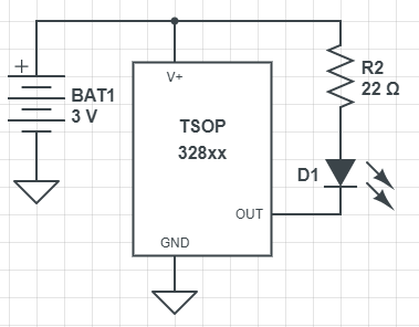
Ground: Voltage Low-point
This schematic is drawn a bit different. There is a new symbol which looks like a down-arrow. That symbol represents ground. Even though the schematic doesn’t show those two ground points (the negative side of the battery and the GND pin of the IR sensor) as connected, they are considered connected. Well, they are considered connected to ground. You’ll see this as a common way to shown components connected to ground in a schematic. It is somewhat of a shorthand since you don’t have to draw a connection from the GND pin over to the negative side of the battery.
Also, you can see that the pins of the IR Sensor are arranged differently in the schematic than they exist on the real component. This is simply to allow the schematic to be drawn in the cleanest possible way. In real life, as you wire up your circuit, you may find that you have to have wires bent in various ways to get the proper connections and that is normal.
Let’s talk about how this might work on a breadboard, because it can be a little confusing.
Ground Rail of Breadboard
On your breadboard, we can obviously use the ground rail. You can connect one wire from the negative side of your battery to the ground rail. Then, each connection that needs to go to ground (in this case, it is just our one pin from the IR Sensor) simply connects to the ground rail. If there were other components in the circuit which need to get ground also, we would simply connect them to the rail. That’s because once the ground rail of the breadboard is tied to the negative side of the battery, the entire rail becomes ground.
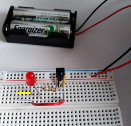
Here’s what my circuit looks like on my breadboard.

And here it is when I press a button on my television remote which sends IR (infrared).

The small red light on the remote is provided by the remote maker because they know people cannot see IR (infrared) and so wouldn’t know if the remote is working or not without the light.
Of course, in the picture, I have the remote very close so you can see it but this particular sensor will pick up IR from over 30 feet away.
Once you know your remote is working and you’ve built the circuit, then point the remote at the IR Sensor on your circuit and press and hold a button on the remote. When you do, you should see the LED in the circuit you’ve built light up.
More Detailed Understanding of the IR Sensor
Let’s take a closer look at what happens when the IR Sensor detects infrared light.
Datasheet Provides Great Details
To better understand how this circuit and the IR sensor works, we need to examine more details of the IR Sensor. Let’s take a look at the datasheet which provides numerous details.
However, don’t get overwhelmed by the document. Instead, just focus on the parts you can understand and over time you will become more familiar with datasheets and they won’t be as imposing. I will walk you through the parts of the datasheet that are meaningful to us or our discussion.
Three Connections are Three Pins of IR Sensor
First of all, keep in mind that the three connections on the schematic component are the three legs (pins) on the actual IR Sensor.
The datasheet lets us know what each of the pins represent when you hold the IR Sensor in the same orientation.

Pins Defined
So when you are facing the part of the IR Sensor which looks like a dome or bubble, then the pin on the left is pin 1 (output) the middle one is pin 2 (GND = ground) and the right one is pin 3 (Vs supply voltage).
That is great information because you don’t want to get the pins backwards and accidentally apply voltage to the output pin and connect pin 3 to ground because the device will obviously not work that way.
Of course just like datasheets for other components, this one provides you with information about maximum and minimum voltages and currents.

These are important so we don’t supply to much voltage or current to the device and possibly destroy it and so we understand that if we supply less than the minimums, then the device isn’t going to work as expected.
In our case, we are using two AA batteries supplying approx 3V.
Let’s do some measuring and see what actual values are on the board at different points.
Basics of How this Circuit Works
The way this thing works is that the voltage on pin 1 (output) is held high until IR (infrared) hits the sensor.
Voltage is About Difference
Since the voltage is held high, that means there is no current is going through the LED. That’s because while the voltage is held high on pin 1 (output), there is no voltage difference between the legs of the LED : they are both basically at the same voltage. However, when the infrared light hits the IR sensor, then internally the voltage is turned off (voltage is driven low). When the output pin (pin 1) is driven low, a voltage differential occurs between the two legs of the LED and current flows as long as the sensor is receiving infrared light.
This is exactly what we’ve learned about voltage in the previous chapters. A voltage difference has to occur for current to flow. In the past, we have seen that a battery may supply 3V and then we create a circuit that flows toward 0V (ground). However, if there is no pressure difference between the battery and the other point in the circuit, then no current will flow.
The IR sensor uses this exact principle of electricity to resist the flow of current until IR is detected. When the IR is detected then voltage is pulled (or driven) low on the output pin which creates a voltage difference and allows current to flow.
It’s a great idea that you will see repeated in electronics.
There’s more information in the datasheet that can help us understand how the IR sensor is able to do this.

As with many diagrams when you first see it, you may be completely confused. The way to go about this is to attempt to pick apart the pieces that you probably do know. For example, I see a 1, 2 and 3 and I’m guessing that those are the pins of our component.
There are a couple of new schematic symbols here that you haven’t seen before. Over on the far left, there is a diode symbol that includes arrows pointing in at the diode.
We know that a diode symbol with arrows pointing away from the diode ( ) are LEDs
so you may have guessed that this ( ) is the IR sensor. The incoming arrows represent the incoming infrared signal.
We can see from this block diagram that the IR sensor picks up a signal and it goes through a bunch of things which are part of the circuit (input, AGC, Band Pass, demodulator and a control circuit). I don’t know what all that is either and it’s beyond the scope of what we need to talk about.
However, if we look at the far right of the block diagram, there are a number of clues that we can work out to better understand how the IR sensor works.
Over on the right, I see a 30K Ohm resistor (30,000 Ohm) which is connected between pins 1 and 3.
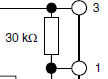
Keep in mind that this is a block diagram so it is using pseudo-schematic symbols and the resistor is shown as a block instead of the normal zig zag line. I know that is a resistor simply because the block diagram shows the Ohm symbol representing resistance.
That same resistor is also connected to another component which, with a small amount of knowledge we’ll gain now, helps us to understand what this IR sensor component really does.

This component which includes the outward pointing arrow (at the bottom), the black rectangle and the line that attaches to the black dot (connection point) at the bottom of the resistor is a transistor.
The top leg of the transistor is connected to the resistor and pin 1 of the IR sensor.
Here’s what a transistor looks like on a regular schematic all by itself.

The schematic makes it a bit more clear that the transistor has three connection points. That is even more clear when you see a real transistor, because it has three legs (or pins).

This is a BJT (BiPolar Junction) transistor of NPN type. There are also BJT transistors which are PNP types also. The P and N are types of materials which are able to control the flow of current and those materials are the magic of how transistors were invented. The N and P materials are types of semiconductor materials. Those materials conduct under some circumstances and insulate (don’t conduct) under others. That’s why they are called semi conductors -- sometimes conduct and other times don’t.
The 2N3904 is the part number and there are other transistors with different part numbers (2N2222) with slightly different characteristics to them. They have different electrical characteristics which you can find on their datasheets but they work in similar ways.
However, none of that matters so much to us right now. What matters is that the transistor has three pins which are named the base, collector and emitter.
Basically, for the NPN type works so that when the voltage on the base is low then no current flows between the collector and the emitter. That’s what matters to us, because as we said, the IR sensor does not allow current to flow by keeping voltage high on pin 3 until it senses IR.
This is Like a Switch
Keep in mind that the transistor is acting just like a switch. Instead of creating an open (disconnected) place in the circuit, it doesn’t allow current to flow for other reasons. Because of the properties of the semiconductor, it doesn’t allow current to flow until a voltage appears on the base pin of the transistor.
In this way, the transistor acts like a voltage-activated switch. When there is a voltage on the base, then the current flows. When there is no voltage, then no current flows.
Summary of Entire Sensor
So we can see that when there is no IR incoming to the sensor then no voltage is present on the base pin of the transistor. However, when IR comes into the sensor, the electronic components somehow convert that IR into a voltage which appears on the base pin. When that voltage occurs on the base pin of the transistor, then current that is present on the collector pin from the input voltage (pin 3 of the IR sensor) can flow. When it flows, it goes through the 30K Ohm resistor and out pin 1 (output). When current flows from pin 1 of the sensor, the current as we have it connected flows into the positive pin of our LED and out the negative pin into the resistor and out the ground pin (pin 2 of the IR sensor). It can flow because the ground pin is no longer at 3V (and no voltage difference) but is now (with IR present) at 0V.
The important thing to keep in mind is that the IR sensor and its circuit act like a switch. And since it acts like a switch that is activated by IR, you can send IR over a distance and use this component like a remote switch. This helps us to begin to automate our circuits.
Let’s wrap up this chapter by trying to measure the voltage across the LED in both states (with IR present and without). However, as we do that, we will see some results that seem odd at first but will make sense after we discuss how the IR remote and our multimeters actually work.
Let’s Try Measuring Voltage When IR Hits Sensor
To measure the voltage that is present, you can simply:
- set your multimeter to measure DC voltage
- clamp each of your probes onto the appropriate LED legs (positive to positive, negative to negative)
- measure with no IR present
- aim remote at the IR sensor and press a button
Here’s what mine looks like when I set it up.

I’ve simply clamped my probes on to make it easier to take the pictures and to insure the probes have a solid connection to the LED.
Here’s the first measurement with no IR present. You can see that the meter is actually measuring 0.7mV. It’s a negligible amount that is because of the way the meter works.

How Measuring Voltage Works On a Meter
Measurements are actually averages of a time series. The voltage meter is actually measuring many times a second and then averaging those values. This also explains why our next measurement with IR present seems to register a voltage that is actually lower than the required forward voltage of the LED.
Here’s the snapshot I took when I pointed the remote at the sensor and pressed a button.

You can see that the meter is only showing 122.9mV. However, we know that these red LEDs require about 1.8V before they will light up. Why would this be happening?
IR Remotes
First of all, we have to understand how IR remotes work. When you press a button and the IR LED flashes in the remote to send a signal to the receiver (usually a TV), the LED actually flashes in a pattern. The pattern is similar to sending morse code. The IR remote (transmitter) is actually sending some patterns of flashes that is different for each button you send so that the Television or other device at the other end can decode and understand which button you have clicked. The point here is that when you push a button, the IR LED is flashed hundreds of times a second.
Since the IR is being flashed, the IR sensor is fast enough to pick up each of the flashes and only generates a pulse of voltage for each flash. That means that the voltage across the LED coming from the output pin of the IR Sensor is only on intermittently for some milliseconds.
That in turn creates an overall voltage that is enough to keep the LED lit, but which when measured by the sensitive meter, it knows that the average voltage that is only 122mV.
Let’s try measuring the current that flows through the LED.
Measuring Current
Keep in mind that to measure current the multimeter has to become a part of the circuit. In other words, we allow the current to flow right through the multimeter. To set it up, I pull the end of the red wire out of the breadboard and connect it to the red probe. Next, I clamp the black probe onto the first (positive leg) of the LED.
Marked with yellow lines in the next image.
You can see that before IR is present (no remote), the meter measures a nominal current (0A).

When IR is present, you will see an actual current.

In this case, the meter measures 0.73mA. That’s quite a bit less than these LEDs are rated for, but again, this is an average that is occurring as the circuit is turned on and off very quickly by the IR sensor.
We’ve worked through a lot and we’ve learned a lot. The most important thing is that all of these concepts you are learning help to build a solid foundation because they are things you will continually see in all your future projects and they help move you toward self sufficiency so you can build and design your own circuits.
Next Time: Chapter 4
Here's a quick list of what we'll cover next time.
- Resistors
- color coding
- Measure resistance with meter
- Power (P=EI) and heat dissipation
- Combining resistors in series in circuits
- Combining resistors in parallel (show formula)
- How resistors can help to divide voltage (to step voltage down)
- Potentiometers (variable resistance) Show turning off LED by increasing resistance
- Capacitors
- Ability to store a charge is known as capacitance
- Battery creates electric field by created voltage differential on capacitor plates. Then since there is a voltage differential, when you remove the battery the electrons that have built up will flow from higher side to lower side.
- Capacitance is measured in Farads (F)
- Calculate time to charge a capacitor T = R x C (Time = Resistance(ohms) x Capacitance (farads))
- One farad capacitor can store one coulomb of charge at one volt. That means it could supply 1 Amp of current for one second.
- Transistors
- Build flashing circuit with transistors and capacitors
History
- 18th February, 2018: First publication