
JavaScript-Based IoT/WoT Development with the ESP8266
4.48/5 (8 votes)
As opposed to the less powerful Arduino, the competitively priced and WiFi-enabled ESP8266 supports the Web-of-Things (WoT) since it can be programmed in JavaScript.
- Download Mongoose Flashing Tool Build for Raspbian - 21.7 MB
- Download Mongoose-IoT Firmware with DHTxx JavaScript Support - 784 KB
- Download DHTxx C/C++ Source Code - 719.2 KB
This tutorial and other interesting online tutorials and books on web development are published by web-engineering.info. Check our WoT/IoT Articles section.
The ESP8266 has gained a huge popularity over the last few years, since it provides a powerful MCU, SPI Flash, 2.4GHz 802.11 b/g/n WiFi capabilities and relatively small power consumption, all for just a few dollars. As opposed to the Arduino, due to its more powerful resources, the ESP8266 allows to run JavaScript programs. This article focuses on discussing how to use JavaScript to program an ESP8266. Currently, two firmware versions allow JavaScript code execution on a ESP8266 modules: Mongoose-IoT (that we'll discuss about in this tutorial) and Espruino for ESP8266.
With a single small and cheap board, it is possible to have a JavaScript interpreter, WiFi client, WiFi router, HTTP client and server and GPIOs control, therefore allowing to read sensors, control actuators and use human interface devices, such as displays, buttons or joysticks.
Meet the ESP8266
Various modules built around the ESP8266 IC are available, and the most common 12 standard modules are shown in Figure 1.

These modules use the 802.11b/g/n WiFi standard, operating at 2.4 GHz. It means they can connect to a standard WiFi network, such as the ones provided by an WiFi router, WiFi repeater or access point (AP). No need for special communication channels or frequencies, such as the 433MHz band required by some wireless modules.
Choosing the Appropriate ESP8266 Module for a Project
Having multiple variants of ESP8266 module, comes the question: "which one should I use ?". There is no perfect answer for this question, and it highly depends on what you are using the WiFi module for. These are not just "blind" WiFi communication modules, but small development boards, containing a programmable MCU and builtin GPIO pins, thus it can do tasks similar with the ones possible with the Arduino boards, but being much faster and in some sense more capable. We see three main points to be considered when choosing an ESP8266 module for a specific project:
- usability on a breadboard: most of the times we prototype on a breadboard, therefore we should be able to easily connect (or plug) these modules to such a board. Some of the modules, such as ESP02, ESP03 and ESP05 (see Figure 1) are breadboard friendly, having a pitch of 2.54mm (the distance between two pins). Other modules, such as ESP07 or ESP08 have a pitch of 1.27mm, thus you'll only be able to use them with a breadboard when using an adapter. Last, other modules, such as ESP01 have a pitch of 2.54mm, but they have a two rows header, which makes it impossible to be used with a breadboard, because of the implied short-circuit between the pins. Notice that some of the breadboard friendly modules have only a "half-way" pin connections, e.g., ESP02 module. Such connections are somehow harder to solder, specially for a beginner. Our tip for the ESP02 module: plug the pin headers into a breadboard, align the module on top of them, then solder.
- flash memory size: the ESP8266 modules come with permanent flash memory ranging from 4MBit (512KB) up to 16MBit (2MB), but some may even go up to 128MBit (16MB). In many cases, it is also possible to increase the flash capacity of such a module, but for this, one needs good soldering skills to remove the old flash IC and solder the new one, and usually the price of the flash IC bought in small quantities is about the same as for the price of the complete ESP8266 module (or even more!), thus defeating the purpose. Excepting the case of ESP06, ESP07, ESP08 and ESP12E/F modules, where a hard to remove metallic shield covers the CPU and flash ICs, one can simply check the flash size by reading the text on the 8 pin black IC soldered near the MCU (which is the square black IC with pins on all four sides). For example, if the number on the flash IC starts with 25Q80 then it is a 8MBit Flash, while if it starts with 25Q40 then it is a 4MBit one. For our purpose, a minimum of 1MB (8MBit) Flas is required, but we recommend 4MB+ (16MBit+).
- MCU features: these modules are driven by a low power 32-bit RISC CPU (Tensilica Xtensa LX106) running at 80 MHz. It has 64 KB instructions RAM, 96 KB data RAM, it and supports external QSPI flash - 512 KB to 4 MB (but also up to 16MB is supported). Up to 16 GPIO pins are available, from which one has 10Bit ADC capabilities, and supports I2C, I2S, SPI and UART communication protocols. All these features are quite important if you are using the ESP8266 module as standalone controller board. However, if the ESP8266 module is used as an UART WiFi interface only, then you'll not really use the GPIO pins, so you may ignore this when selecting the board that suits your needs.
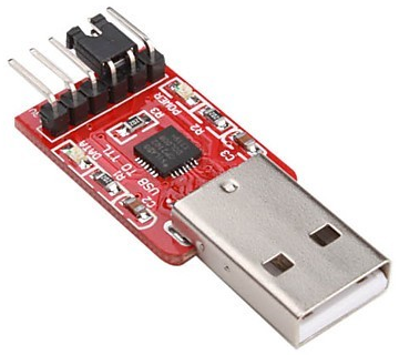
Note: for being able to write a new firmware or to communicate with an ESP module by using a computer, you'll need a USB-TTL module, such as the CP2102 IC based one, shown in Figure 4. You'll need to connect the TX pin of the USB-TTL module to the RX pin of the ESP module, and the RX pin of the USB-TTL module to the TX pin of the ESP module. For being able to flash a new firmware, but NOT when using the ESP module in normal mode, you'll also need to connect the GPIO0 pin of the ESP module to ground then perform a power cycle.
Standalone User-Friendly ESP8266-Based Modules
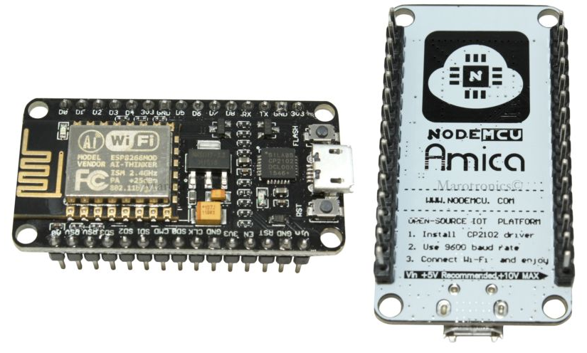
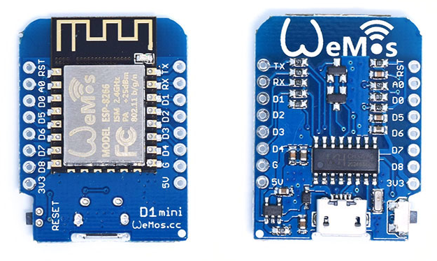
Other ESP8266 based modules are designed with "make it simple, for anyone" in mind. Usually these provide a two rows breadboard friendly PCB, with USB (usually via a micro USB cable) connection, both for providing power (also by using a standard micro USB charger) and if needed, also for the communication with a PC. Figure 2 shows the NodeMCU V2 board, designed by Amica, providing an on-board CP2102 USB-TTL IC, allowing to communicate with the PC via the same micro USB cable that also used to power it. Figure 3 shows a WeMOS D1 Mini module, designed to use stackable expansions boards (similar with the Arduino Shields), thus being able to attach various sensors, actuators or even OLED LCDs.
Some Words Before Getting Started...
Before going further with the reading and following the tutorial instructions, is good to know that:
- we are going to use an ESP8266 NodeMCU V2 board, produced by Amica (see Figure 2), which means: a) there is no need to put it to "flashing mode", since this happens automatically, the bundled USB-TTL CP2102 IC takes care of this task; b) is powered via the micro USB cable directly from an USB port, the same port being also used for the communication with the module, if this is needed (e.g., for programming the module)
- the further provided instructions presumes that a Raspberry Pi 2/3 board running Raspbian is used, but other Linux distribution, on either a RPi 2/3 board or a PC works too, however some differences may occur with respect to some commands and Linux repositories used to obtain the required components
- the ESP8266 12E/F modules (see Figure 1) should work well, as an alternative to NodeMCU board, but its GPIO0 pin must be pulled LOW to set the module to "flashing mode", task required ONLY when the firmware needs an upgrade, and then a power cycle between the "flashing mode" and "normal operational mode" is also required - other ESP8266 modules may also work, but usually they either have less exposed GPIO pins or they are not breadboard friendly
- the SPI Flash IC of the ESP8266 module must be 1MB+, otherwise the module will not work properly or may not work at all
- a Windows PC can also be used, and this makes the process of writing the firmware to ESP8266 module easier, but various other changes are needed for being able to build the Mongoose-IoT firmware from source code, when you need custom functionality which requires firmware code changes - unfortunatelly, compiling the Mongoose-IoT firmware on a Windows machine is a real pain
- further on, we'll use MFT as a short name for the "Mongoose-IoT Flashing Tool" software, ESP as a short name for the ESP8266 module (full name is used if needed to make distinction in some cases, when just ESP is confusing) and RPi as a short name for "Raspberry Pi 3 Model B".
Flashing the Standard Mongoose IoT Firmware Using a Raspberry Pi
For being able to execute JavaScript code on your ESP module requires to upload the Mongoose-IoT firmware. It uses the V7 JavaScript engine and allows to execute standard JavaScript code. Notice that only a subset of the standard JavaScript is supported, and some of the features are stripped down, so the V7 engine "fits" on the ESP module. For example, some String related check/manipulation methods (e.g., startsWith and endsWith) and the new ECMA5 features may not be (at all or fully) supported. However, it comes with additional features, which are not available as part of the standard JavaScript core, but a being available on NodeJS (i.e., stripped down modules or core functionality), such as the HTTP client (allowing for HTTP requests) and HTTP server capabilities.
Build the Mongoose Flashing Tool Application
The latest standard Mongoose-IoT firmware version can be obtained by using the MFT software. Compiling and building it from source code requires quite some time (about 2+ hours) to complete, and lots of space on your RPi storage (3GB+, but most of it can be recovered at the end), because it needs to download and compile the Qt Framework. The following steps guides you through the process of installing MFT on your RPi:
- make sure that your RPi has internet connection (either WiFi or wired connection)
- install dependencies required further in the build and compile processes:
# sudo apt-get install build-essential git python-git wget libglib2.0-dev libudev-dev libftdi-dev libfontconfig1-dev libjpeg-dev libssl-dev libicu-dev libjpeg-dev libxcb-xinerama0-dev libxcb-icccm4-dev libxcb-image0-dev libxcb-keysyms1-dev libxcb-render-util0-dev libxcb-shm0-dev libxi-dev libxrender-dev x11proto-render-dev qt5-qmake libqt5serialport5-dev libxcb-util0 libffi-dev
- configure, build and install the Qt static libraries by executing:
# wget -c http://download.qt.io/official_releases/qt/5.7/5.7.0/single/qt-everywhere-opensource-src-5.7.0.tar.gz
# tar xzf qt-everywhere-opensource-src-5.7.0.tar.gz

# cd qt-everywhere-opensource-src-5.7.0

# ./configure -make 'libs tools' -static -prefix /opt/qt5 -opensource -confirm-license -skip qt3d -skip qtcanvas3d -skip qtdoc -skip qtlocation -skip qtscript -skip qtmultimedia -skip qtsensors -skip qtwebengine

# sudo nice make -j4

# sudo nice make -j4 install

# sudo /opt/qt5/bin/qmake && nice make -j 4
...now take a cafe and watch some YouTube videos, this task takes quite some time to complete (approx. 80 minutes on our RPi 3B board). Some Qt5 extensions were excluded since we don't really need them for our purpose and thus the compilation time is cut down.
Note: each line starting with a dash (#) is a new command, and you should not write the # when executing this. You can execute the commands one by one or as a batch, on your RPi console of via SSH. - ensure that your beloved RPi does not overheat during the above tasks (specially when building Qt), so from time to time check the CPU temperature by using
sudo /opt/vc/bin/vcgencmd measure_temp
and make sure that the temperature stays below 80°C / 176°F. Blow some air by using a cooler or place your RPi somewhere in a good ventilated area. In our case the temperature did not exceeded 60°C, on a room with temperature of about 24°C, but a cooler was used to move the air around, because our RPi is a bare board with no heatsinks or any other cooling method.
Note: for single core RPi boards (RPi 1 Model B), do not use the "-j" parameter, e.g.,sudo nice make -j 4(or any other task), since this parameter is being used to specify the number of CPU cores to be used during that task, so it fails with a value of "4" (or any other) when used with single core CPUs (e.g., Raspberry Pi Zero or Raspberry Pi 1 Model B). - clone the Mongoose Flashing Tool Repository - thus getting the latest available source code:
# git clone https://github.com/cesanta/mongoose-flashing-tool.git
in a folder at your choice - enter the newly source code folder, by using:
# cd mongoose-flashing-tool
- execute:
# QT_SELECT=5 /opt/qt5/bin/qmake && make -j 3
to build MFT from source. This step may take some time to complete (about 2 minutes on our RPi 3B) - in case that the above step results in one or all of the build errors:
/usr/bin/ld: cannot find -lEGL
/usr/bin/ld: cannot find -lGLESv2
then your OpenGL static libraries cannot be linked, probably because are not found, because normally their shared versions are available on Raspbian. To solve this you need to edit themongoose-flashing-tool/src/Makefilefile, by using whatever editor you like. Notice that this file DO NOT existst before trying to compile MFT, you can only find it afterwards (even if you get the error, the file must be there). In this file, find the following-lEGLand-lGLESv2and delete them. Then at the end of the line where you found these two, add the following:-Wl,-Ddynamic -L/opt/vc/lib -l:libEGL.so -l:libGLESv2.so, then save the file and execute theQT_SELECT=5 /opt/qt5/bin/qmake && make -j 3command again (make sure that you are in themongoose-flashing-toolfolder and NOT in itssrcsub-folder when doing this). - at this point you must connect the ESP module (e.g., NodeMCU, WeMOS or a standard one with an attached USB-TTL bridge) to an USB port of your RPi board,by using a corresponding USB cable and any of the USB ports of your RPi board
- start the MFT application by executing:
# cd src
# ./MFT
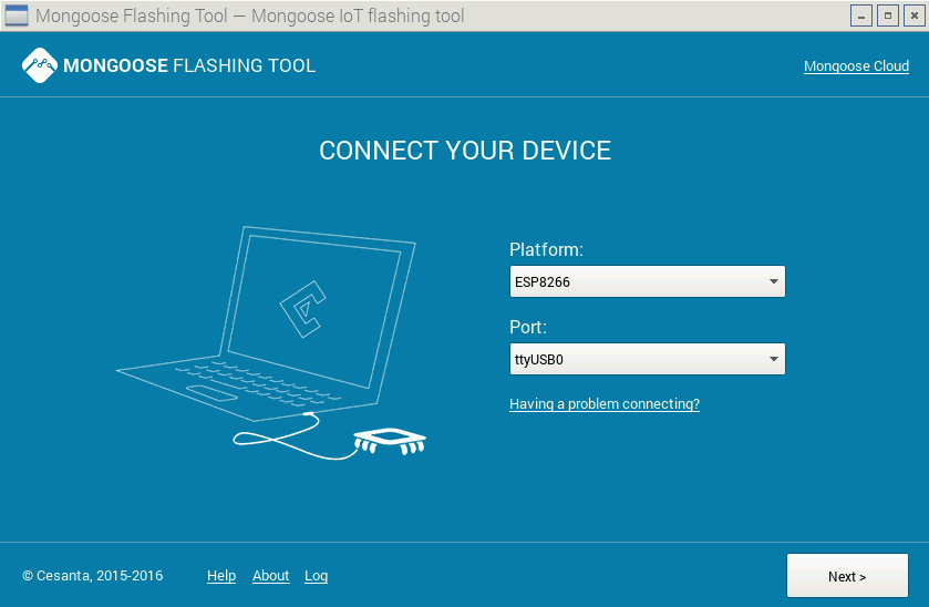
and the application must start in GUI mode and should detect the module type (ESP8266). Make sure that you select the correct port (e.g.,ttyUSB0in our case), then follow the instructions, as also shown in Figure 5, Figure 6, Figure 7, and Figure 8. - if your ESP module refuses connection for firmware update (it happens normally only with the basic ESP modules, see Figure 1, but should not be the case for NodeMCU and WeMOS D1 Mini boards), it usually means that the module did not entered "flashing mode", so you may want to check if the GPIO0 pin is pulled LOW (do this task without supplying power to the board!), i.e., connected to GND rail, and make sure to power cycle the module after pulling LOW the GPIO0 pin
- now you can remove the source folders for the Qt5 library, this freeing up 3GB+ on the RPi SD/MicroSD card, by executing:
# rm -rf qt-everywhere-opensource-src-5.7.0
from the parent folder ofqt-everywhere-opensource-src-5.7.0folder. If permission denied errors occurs, then execute the command withsudo.
If you find the build process too complicated, but still want to try the ESP8266 firmware, then download the compiled MFT application for Raspbian (tested on 20 October 2016) from the link below, or use the download link from the top of this page. Unzip the archive by executing unzip mongoose-flashing-tool.zip, and give execution rights to the src/MFT application, by using sudo u+x src/MFT from the mongoose-flashing-tool folder. Finally, install the libxcb dependency library, by using sudo apt-get install libxcb-util0. Now you can run the application by using src/MFT from the mongoose-flashing-tool folder or simply ./MFT from the mongoose-flashing-tool/src folder.
Download Mongoose Flashing Tool (MFT) Build for Raspbian
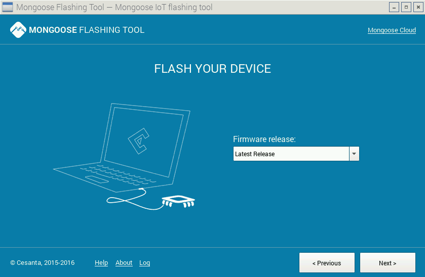
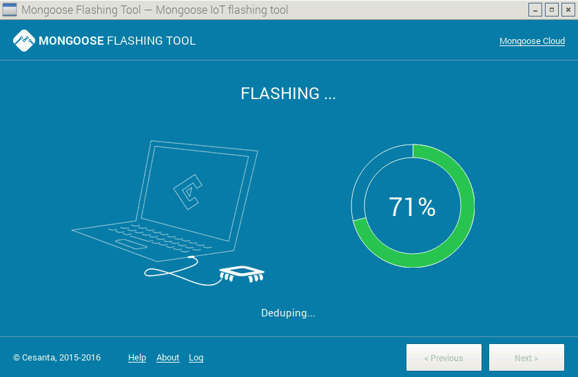
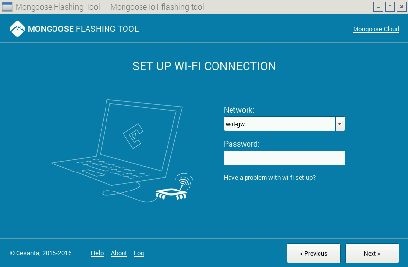
Connecting the ESP8266 module to a WiFi network (see Figure 8), is optional, and you can do this later when the module needs access to Internet or Intranet. Therefore, after the step shown in Figure 7 you can already close the MFT application.
First JavaScript Tests on ESP8266
Lets test now our new JavaScript toy! For this, from the folder mongoose-flashing-tool/src, execute:
./MFT --advanced
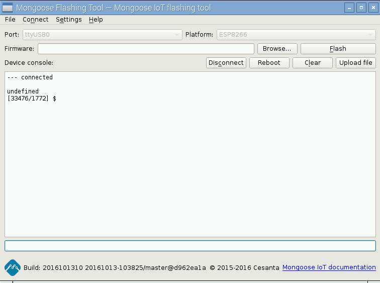
which opens the same MFT application, this time in an advanced mode where you can interact with the ESP module, using some kind of console like style (see Figure 9). Then, select the communication port (should be the same as the one used when writing the firmware), and click the Connect button. If all went fine, you must be connected to your ESP module.
As a simple test, lets check the current configuration of your ESP module, currently running on the Mongoose-IoT firmware. For this, in the MFT Console, write Sys.conf then press Enter. As result, the serialized JavaScript configuration object is shown (see Figure 10).

One more test we like to do, is to upload a JavaScript file, containing some code that we like to execute on ESP8266. For this, create a file named app.js on a folder at your choice, then using a text editor, open it and copy/paste the following simple test code:
function sum(a, b) {return a+b;};
console.log( "The sum of 123 and 456 is: " + sum( 123, 456));
Use the Upload File button, and and select the app.js JavaScript file to be uploaded to your ESP8266 module. Reboot the module, using the Reboot button, then in a few seconds, after some initialization messages, you should see:
The sum of 123 and 456 is: 579
as the result of executing the JavaScript code from app.js file.
Note: the JavaScript code MUST be in a file named app.js, and you can't just use any filename you like, because after booting, the firmware runtime looks for this specific file, and if is found, the JavaScript code is executed. Note that if you have JavaScript errors in your code, the module may behave strange, like continuously resetting itself, and in some cases, the only way to have it back working is to upload the firmware again!
You may also want to check this YouTube video showing the basics steps in using the Mongoose-IoT Cloud Service.
Build and Flash the Mongoose-IoT ESP8266 Firmware Using a Raspberry Pi
Since we like to add more functionality into the existing Mongoose-IoT firmware, discussed later in this article, we need to compile the firmware and flash it to the ESP module. For this, we need to prepare our system by following the steps below:
- install docker, if not already existing in your system:
# sudo curl -sSL https://get.docker.com | sh
- allow user to use docker (add user to docker group):
sudo usermod -aG docker pi
Notice that we have used the user with namepiin the example above, if is the case, replace this accordingl - start the docker service:
# sudo systemctl daemon-reload
# sudo service docker start
- clone the git repository of the Mongoose-IoT Firmware project:
# git clone https://github.com/cesanta/mongoose-iot
- enter the ESP8266 firmware project folder:
# cd mongoose-iot/fw/platforms/esp8266
- edit the Makefile.build and make sure that the following parameters are set:
APP_FS_PATH ?= $(REPO_PATH)/fw/platforms/esp8266/fs
MG_ENABLE_JS ?= 0
CREATE_RAW_FS ?= 1
- build the firmware:
# sudo make
Notice that this task may take some time to complete, for the first time, since variousdockerimage packages needs to be downloaded and extracted on your machine - when the build process is complete, the resulting firmware zip archive file is:
mongoose-iot/fw/platforms/esp8266/firmware/mongoose-iot-esp8266-last.zip - open the MFT application in advanced mode, by executing:
./MFT --advanced
from themongoose-flashing-tool/srcfolder - connect to the ESP module by using the
connectbutton, after selecting the correct communication port (e.g.,ttyUSB0), then use theFirmwwaresection to select the firmware zip file created above, and press theFlashbutton - in a few seconds, the flash process must be completed, now reboot the ESP module by clicking the
Rebootbutton - test if the module works as expected: execute
Sys.confin the MFT console, and you should see current configuration settings.
You can also download the "ready to flash" Mongoose-IoT Firmware for ESP8266 with DHT11/21/22 JavaScript support by using the download button below:
Download Mongoose-IoT Firmware for ESP8266 with DHT11/21/22 JavaScript Support
Expose Custom JavaScript Global Methods and Objects
Note: the complete source code for all the examples discussed in this section is available on our GitHub project page. You can also download the code using the links from this article, however, it may be outdated after some time, so we strongly recommend our GitHub project page instead.
Some components, such as DHT22 / AM2302, temperature and humidity sensor, but not only, are harder to be read directly from the JavaScript code with the Mongoose-IoT firmware. This happens because the MCU is simply not fast enough for the JavaScript interpreter, so we can't deal with the very small pulses (under 20μs) we need to measure on the code, for being able to communicate with such components. The alternative and better approach is to write custom C/C++ code as part of the Mongoose-IoT firmware, and expose some objects and methods to JavaScript, thus being executed by the native firmware code, which is so much faster.
First we define a flag which allows to enable of disable the DHTxx library, so in case that for a project you don't need such a sensor, is possible to exclude this code from the firmware simply by using a flag. Notice that the firmware needs to be compiled/rebuild after adding or dropping the parameter. The following C/C++ code is part of the fw/platforms/esp8266/user/v7_esp_features.h file:
#ifndef CS_FW_PLATFORMS_ESP8266_USER_V7_ESP_FEATURES_H_
  #define CS_FW_PLATFORMS_ESP8266_USER_V7_ESP_FEATURES_H_
  #define V7_ESP_ENABLE__DHT
#endif
Note: only the marked code line is new (added by us), the rest of the code already exists as part of the fw/platforms/esp8266/user/v7_esp_features.h file.
The next step is to modify the file fw/platforms/esp8266/user/v7_esp.c by considering the code shown below:
#include "fw/platforms/esp8266/user/dht.h"

#ifdef V7_ESP_ENABLE__DHT
  static enum v7_err DHT_read(struct v7 *v7, v7_val_t *result) {
    v7_val_t sensorTypeArg = v7_arg(v7, 0);
    v7_val_t pinArg = v7_arg(v7, 1);

    // validate the first parameter - the DHT sensor type (11, 21, or 22)
    if (!v7_is_number(sensorTypeArg) ||
        (v7_get_double(v7, sensorTypeArg) != 1
        && v7_get_double(v7, sensorTypeArg) != 2
        && v7_get_double(v7, sensorTypeArg) != 3))
      return v7_throwf(v7, "Error", "Parameter 1, must be one of Dht.TypeEL.DHTxx.");

    // validate the second parameter - the GPIO pin number
    if (!v7_is_number(pinArg))
      return v7_throwf(v7, "Error", "Parameter 2, must be a GPIO pin number.");

    uint8_t pin = v7_get_int(v7, pinArg);
    uint8_t sType = v7_get_int(v7, sensorTypeArg);
    double temperature = 0.0;
    double humidity = 0.0;
    const char* sTypeName = (sType == 1 ? "DHT11" : (sType == 2 ? "DHT21" : "DHT22"));

    // read the DHT sensor and check if the read was a successful
    if (!dhtRead(sType, pin, &temperature, &humidity)) {
      // error reading DHT sensor...normally this is a check sum error
      return v7_throwf(v7, "Error", "Failed to read the DHT sensor!");
    }

    // create the result JavaScript object and append the
    // "type", "temperature" and "humidity" properties, as well as their values
    *result = v7_mk_object(v7);
    v7_set(v7, *result, "type", 4, v7_mk_string(v7, sTypeName, 5, 1));
    v7_set(v7, *result, "temperature", 11, v7_mk_number(v7, temperature));
    v7_set(v7, *result, "humidity", 8, v7_mk_number(v7, humidity));
    return V7_OK;
  };
#endif /* V7_ESP_ENABLE__DHT */
The DHT_read method is responsible to check the parameters provided to the JavaScript Dht.read method. Internally, the dhtRead method will be called - it is responsible for the communication with the sensor, as discussed further in this section. Finally, a JavaScript anonymous object representing the JavaScript Dht.read method response is created. It is stored in a pointer, the last parameter of the DHT_read method. Notice that the DHT_read method returns V7_OK or throws exceptions, depending on the case. Also notice that DHT_read is a name that we choose, so you are free to change it with whatever you find appropriate, but remember to change every reference in the code.
Further, in the same fw/platforms/esp8266/user/v7_esp.c file, we modify the init_v7 method code as shown below:
void init_v7( void *stack_base) {
  // this code is compiled and becomes part of the firmware, only if the
  // V7_ESP_ENABLE__DHT flag is used
  #ifdef V7_ESP_ENABLE__DHT
    v7_val_t dht = v7_mk_object(v7);
    v7_val_t typeEL = v7_mk_object(v7);
    // create the Dht global object, accessible in JS code
    v7_set(v7, v7_get_global(v7), "Dht", 3, dht);
    // add the read method to the DHT JS object
    v7_set_method(v7, dht, "read", DHT_read);
    // define the Dht.TypeEL enumeration property
    v7_def(v7, dht, "TypeEL", 6,
      (V7_DESC_WRITABLE(0) | V7_DESC_ENUMERABLE(1)), typeEL);
    // create the Dht.TypeEL.DHT11 enumeration literal
    // {enumerable: true, writable: false}
    v7_def(v7, typeEL, "DHT11", 5,
      (V7_DESC_WRITABLE(0) | V7_DESC_ENUMERABLE(1)), v7_mk_number(v7, 1));
    // create the Dht.TypeEL.DHT21 enumeration literal
    // {enumerable: true, writable: false}
    v7_def(v7, typeEL, "DHT21", 5,
      (V7_DESC_WRITABLE(0) | V7_DESC_ENUMERABLE(1)), v7_mk_number(v7, 2));
    // create the Dht.TypeEL.DHT22 enumeration literal
    // {enumerable: true, writable: false}
    v7_def(v7, typeEL, "DHT22", 5,
      (V7_DESC_WRITABLE(0) | V7_DESC_ENUMERABLE(1)), v7_mk_number(v7, 3));
  #endif /* V7_ESP_ENABLE__DHT */
}
The purpose of this code is to create the Dht JavaScript object (accessible from the JavaScript code running on the ESP module), create the Dht.TypeEL JavaScript "enumeration" (well, emulating an enumeration) and to expose the Dht.read method, so we are able to read the DHT sensor from a JavaScript program.
Notice that we can create objects and object properties for the exposed JavaScript interface, in a similar manner as we do in standard JavaScript code with the help of <a href="https://developer.mozilla.org/en-US/docs/Web/JavaScript/Reference/Global_Objects/Object/defineProperty">Object.defineProperty</a> and <a href="https://developer.mozilla.org/en/docs/Web/JavaScript/Reference/Global_Objects/Object/defineProperties">Object.defineProperties</a>, thus we can make a property read-only, enumerable and provide an initial value to it if required. Datatypes values are obtained by calling the corresponding v7_mk_xxx method, where xxx can be null, object, number or string depending on the case.
It is also important to know that when we use the v7_def and v7_set methods, their 4th parameter is a positive integer, representing the number of characters of the name of the property or method that is created. Failing to set this value correctly, results in the property or method not being recognized in the JavaScript code!
Note: the init_v7 method contains additional code, which should be kept unchanged. In this tutorial only show the new code, required for our custom functionality, but the existing code must not be changed, otherwise the resulting firmware may not work as expected.
Now, we need to write the a C/C++ header file that exposes the method(s) meant to be used by the Mongoose-IoT firmware for the communication with the DHTxx sensor. We create the file fw/platforms/esp8266/user/dht.h that defines the signature of the dhtRead method:
#ifndef DHT_LIBRARY
  #define DHT_LIBRARY
  #include "v7_esp_features.h"

  #ifdef V7_ESP_ENABLE__DHT
   bool dhtRead(uint8_t sensorType, uint8_t pin, double* temperature, double* humidity);
  #endif
#endif
Notice that this header file was already used in the fw/platforms/esp8266/user/v7_esp.c code. Finally, we need to add the fw/platforms/esp8266/user/dht.c file, where we put the code that allows us to communicate with any of the the DHT11/21/22 sensors, for getting temperature and humidity readings:
#include <osapi.h>
#include "v7/v7.h"
#include "common/platforms/esp8266/esp_missing_includes.h"
#include "fw/platforms/esp8266/user/v7_esp_features.h"
#include "fw/platforms/esp8266/user/util.h"
#include "fw/platforms/esp8266/user/esp_gpio.h"

#ifdef V7_ESP_ENABLE__DHT
  static uint16_t waitLHCycle(uint8_t pin, uint32_t* maxCycles) {
    // wait until the pin goes from a digital LOW state
    // to a digital HIGH state, or until the timeout occurs
    // NOTE: this is a helper method for dhtReadByte, to avoid repetitive code
  };
  static uint8_t dhtReadByte(uint8_t pin, uint32_t* maxCycles) {
    // read one byte (8 bits) of data from the DHTxx sensor
    // by using the sensor datasheet which explains what means a bit 1 and a bit 0
  };
  bool dhtRead(uint8_t sensorType, uint8_t pin, double* temperature, double* humidity) {
    // 1) read the 5 bytes of data from the DHTxx sensor;
    // 2) perform a check sum test for data integrity (the 5th byte is the check sum one);
    // 3) decode the 4 bytes of data and transform them to temperature and humidity values
  };
#endif
See the fw/platforms/esp8266/user/dht.c full source code on GitHub or download the full source code archive using the link at the top of this tutorial page.
Lets have a look at the interesting parts only, mainly how to control GPIO pins. Before being able to interact with a GPIO pin, we need to set the pin either for read of write mode, with the help of mg_gpio_set_mode method. It accepts three parameters: 1) the GPIO pin number; (e.g., 5 for GPIO5) 2) the mode, which is one of {GPIO_MODE_INOUT = 0, GPIO_MODE_INPUT = 1, GPIO_MODE_OUTPUT = 2}; 3) GPIO pull type, one of {GPIO_PULL_FLOAT = 0, GPIO_PULL_PULLUP = 1, GPIO_PULL_PULLDOWN = 2}, specifying if the GPIO pin is internally pulled up, down or let floating. The following example makes sets the GPIO5 pin as a digital output and GPIO4 as pulled down digital input:
mg_gpio_set_mode( 5, GPIO_MODE_OUTPUT, GPIO_PULL_FLOAT);
mg_gpio_set_mode( 4, GPIO_MODE_INPUT, GPIO_PULL_DOWN);
Reading the state of a digital pin that was set as digital input is made by using read_gpio_pin method, which returns GPIO_LEVEL_ERR (GPIO_LEVEL_ERR = -1) in case of error, GPIO_LEVEL_LOW (GPIO_LEVEL_LOW = 0) if a LOW status was read and GPIO_LEVEL_HIGH (GPIO_LEVEL_HIGH = 1) if a HIGH state was read. To set the status of a GPIO that was set as output implies to use the set_gpio method, which takes two parameters: 1) the GPIO pin number (e.g., 5 for GPIO5); 2) the state to set the pin to, one of {GPIO_LEVEL_LOW = 0, GPIO_LEVEL_HIGH = 1}. For example, if we like to wait for a HIGH signal on GPIO4 pin (set as digital input in the above example) and write a HIGH state on GPIO5 (set as digital output in the above example) afterwards, we'll use:
<code>
while( read_gpio_pin( 5) == GPIO_LEVEL_LOW);
set_gpio( 4, GPIO_LEVEL_HIGH);</code>
Note: the following two header files are required for getting the above described GPIO operations: fw/platforms/esp8266/user/util.h and fw/platforms/esp8266/user/esp_gpio.h.
To make this new feature available on your ESP module, you'll need to compile and build the source code, then flash the firmware, as shown in Section: Build the Mongoose-IoT Firmware on a Raspberry Pi.
After uploading the new firmware, test the DHT functionality by using the following JavaScript code in the MFT Console, or as part of the app.js file:
Dht.read( Dht.TypeEL.DHT11, 5);
Note: if is the case, replace Dht.TypeEL.DHT11 with Dht.TypeEL.DHT21 or Dht.TypeEL.DHT22, depending on the used DHT sensor type, and also replace 5 (the second parameter) with the corresponding GPIO number, to which you have connected the data pin of the DHT sensor.
The ESP8266's Big Brother: The ESP32
The ESP8266 module got lately a big brother: the new ESP32 module. It is more powerful, but also comes with new features, such as builtin Bluetooth 4.2. In Figure 13 we can see the official ESP32 modules, also named WROOM-32. The following table provides the main differences of ESP32 by comparison with ESP8266.
| Feature / Component | ESP8266 | ESP32 |
|---|---|---|
| MCU | Xtensa Single-Core 32-bit L106, 80MHz | Xtensa Dual-Core 32-bit LX6, 160MHz |
| RAM | 160KB | 512KB |
| FLASH | up to 16MB SPI Flash | up to 16MB SPI Flash |
| GPIOs | 17 | 36 |
| SPI/I2C/I2S/UART/CAN | 2/1/2/2/0 | 4/2/2/2/1 |
| ADC | 1 x 10bits | 1 x 12bits |
| WiFi | b/g/n, HT20 | b/g/n, HT40 |
| Bluetooth | - | v4.2 |
| Builtin sensors | - | temperature, touch |
| Working conditions | -40°C - 125°C | -40°C - 125°C |
| Approximate price | 3-10 EUR, including shipping to EU | 10-22 EUR, including shipping to EU |

Unfortunately, at the moment of writing this tutorial, it is not easy to buy the ESP32 module, since most of the online sources (the vast majority from Asia) report the module as "out of stock". However, we strongly believe that the situation will change soon, and the ESP32 may take the place of ESP8266 modules in new projects, or as improvements of the old projects that requires WiFi or Bluetooth connection and MCU on a single small and cheap module.
Some Points of Attention
The ESP8266 module represents the brain of your projects, but it requires that you take some precautions to keep it safe and be sure that it runs as supposed:
- Most of the ESP8266 modules are powered by 3.3V, thus using 5V or anything more than 3.6V may and will damage your module! Some of the ESP8266 modules, such as the NodeMCU or WeMOS, discussed in this article, allows to power the module board (but not directly the ESP8266 MCU!) by using a USB connector (mini or micro USB ones), thus using 5V (or up to 10V for WeMOS D1 Mini), while a builtin voltage regulator is responsible for converting this down to 3.3V as required by the MCU.
- No matter the input voltage accepted by an ESP8266 module (usually a direct 3.3V input or 5V via USB connector), in most cases the GPIOs pins are tolerant to ONL 3.3V or less positive voltage, meaning that you should never ever provide more than 3.3V nor a negative voltage to any of the GPIO pins.
- The ESP8266 module exposes one ADC pin (expandable by using multiplexing or specialized ICs), allowing to measure analog voltages in the range 0-1V. Do NOT provide more than 1V or a negative voltage to this pin. If more than 1V must be measured, then use a voltage divider circuit or an external ADC IC or module (e.g., ADS1015 12-Bit ADC - 4 Channel) capable to communicate via I2C, SPI or UART. However, some modules, such as WeMOS D1 Mini allows 0-3.3V as input for the ADC pin, since it uses a builtin voltage divider circuit.