Here, we will introduce the concept of Bezier curve, design a true (open, free) type glyphs based on curves and lines, render glyphs in subpixel regime, and implement smooth low pass filters.
Prerequisites
- Knowledge of subpixel rendering on LCD panels
- Good knowledge of x86 assembly and C programming languages
Optimization
Let's Get Started
Bezier Curves
What I did to render a curve on screen is constructing a power series (up to 3rd order) which control the curvature of the path.
In fact, in my curve implementation, I stick to cubic bezier curve. It simply is an equation in form of AX3 + B2 + CX + D.
But it is not all. The design of a curve must follow having four points (a 2D coordination pair such as x and y), where point 0 and 3 are starting and ending points and points 1 and 2 are called control points. The latter points are the tuning of the curvature.
Having long concept short, I will create 4 2D points as an array (e.g., POINTS_2D curve_points[4]) and change them in a way to render a desired curve for me.
For a detailed implementation and description of what I explained above, look at my source code (bezier_curve).
This is how it works in its native non-optimized way:
static void draw_bezier_curve(POINT_2D* p, unsigned int color)
{
const unsigned int bits_per_pixel = 24;
unsigned int bytes_per_pixel = bits_per_pixel >> 3;
unsigned int width = WINDOW_WIDTH_ALIGN(bytes_per_pixel * 512); unsigned char red = color;
unsigned char grn = (color & 0x00FF00) >> 8;
unsigned char blu = (color & 0xFF0000) >> 16;
double xu = 0.0; double yu = 0.0; double u = 0.0;
for (u = 0.0; u <= 1.0; u += 0.001)
{
double A = pow(1 - u, 3);
double B = 3 * u * pow(1 - u, 2);
double C = 3 * pow(u, 2) * (1 - u);
double D = pow(u, 3);
xu = A * p[0].x + B * p[1].x + C * p[2].x + D * p[3].x;
yu = A * p[0].y + B * p[1].y + C * p[2].y + D * p[3].y;
unsigned int px = ((unsigned int)yu * width) + ((unsigned int)xu * bytes_per_pixel);
fb[px ] = red;
fb[px + 1] = grn;
fb[px + 2] = blu;
}
}
As you might guess, there are quite some big steps to optimize the code above still in C. The coefficients A, B, C, and D can be calculated without further calling into function pow. Another critical step would be acquiring x86-SSE assembly into play to further optimize xu and xy calculations and also casting them into unsigned int. The detailed optimization would be neglected here for the sake of not getting too much complex. Of course, later during my SIMD optimization tutorial, we will go through all the mentioned codes.
The following image shows a bezier curve rendered with the use of the upper source code. The four drawn small circles represent the place of 4 bezier curve control points.

Designing a Simple Glyph Based on Only Curves and Lines
A glyph, this is what I would like to concentrate on how to build and render. For simplicity, I would stick to constant sized glyphs for all face-types. With that being said, I implement a 9 x 19 pixel area as a glyph to have a text in 12 pt size. To have something similar to 36 pt, for instance, I simply triple both width and height to have a 27 x 57 px area.
The 9 x 19 is not a random picked value, instead, I followed what had been already done in fonts such as consolas or Times New Roman. Therefore, my approximation is basically perfectly matched to the standard.
In my native C implementation, I consider each pixel to be 24 bits (3 bytes) long. This is, of course, not good for optimization, but truly fine for initial demonstration of the concept. Please note that, during the acceleration of the whole process of a glyph rendering, I will switch to 32 bits per pixel, but this would be left for future.
What would be the actual pipeline towards the task? They are:
- drawing the borders of a face-type with the use of curves and lines
- filling the pixels inside the borders to have a filled face-type (i.e., character)
- distribute the designed face-type into subpixels (usage of single R-G-B elements of LCD panels)
- calculating how much of each subpixel has been filled with the character to perform anti-aliasing
- applying the RGB-YUV-RGB space conversions to filter (smooth) the character
- rendering the result to the screen
If you look at the whole steps enumerated above, you'll notice that it takes the font rasterizer engine (our software) to be busy for several ten miliseconds to only render a single character on screen. As being said several times, for the purpose of demonstration, it is truly fine. Later on, I will get the hand dirty on how to accelerate everything in the pipeline with a bit of C code modification and using x86-SSE optimization, therefore, stay tuned for the coming tutorials.
STEP 1
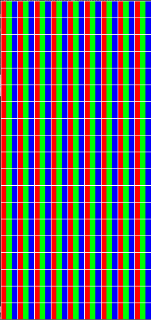
Design a working place. I scaled up my 9 x 19 pixelized area to 216 x 456 px area (24 times scaled up) to have a good look at what I am doing. Since I have 24 times scaling, it simply means, I assigned every 8 pixels to represent an R, G, or B subpixel element. Then I painted them accordingly and clarified the subpixels and pixels borders. You can have a look at the image in the following and try to count 9 x 19 px in my design.
STEP 2
I drew some straight lines and curves to design the letter 'a'. It would be a lot of trial and errors to fix all the points to their positions and also to find a good-looking curve. I am quite happy with my letter 'a' and you can have a look at what I designed so far.

In my font_rasterizer source code, I have everything at hand to look at. As a side note, for later implementation of character filling, we need a way to signal our lines and curves. We need a flag for each line and curve to signal the engine what is the direction of the line or curve. You need to label them as being UPWARD, DOWNWARD, RIGHTSIDE, or LEFTSIDE. With this in mind, we would later be able to decide where to fill and where not to bother to fill in order to construct our face-type.
I assume it is a bit misleading and unclear now, what I explained regarding labelling each line or curve for its direction, but believe me, there is no other ways to decide where is inside a face-type and where is outside. Fine details come in the next step.
STEP 3
One of the biggest challenges in type-face design is to fill the pixels inside the borders defines with lines and curves. For this reason, we define a set of flags to label each element. There is one very important rule to be considered. Only pixels laying in between one element (i.e., line or curve) labelled as CONTOUR_DIRECTION_UP in its left side and an element with label CONTOUR_DIRECTION_DOWN in its right side are supposed to be painted. Think about an example for a moment (with the help of the following image). Suppose there is a standing rectangle that should be filled. We have two vertical lines and two horizontal lines to define the borders of this rectangle. The left vertical line was labelled as CONTOUR_DIRECTION_UP and the vertical line in the right side was CONTOUR_DIRECTION_DOWN. Whatever pixels are in between these 2 lines have to be filled. If there would be two rectangles next to each other, we are able to paint pixels between vertical lines of the leftmost rectangle, then there are pixels between right vertical line of the left rectangle and the left vertical line of the right rectangle that should be untouched. This can be only done since the labelling of lines now follows CONTOUR_DIRECTION_DOWN - CONTOUR_DIRECTION_UP and we invalidate this configuration for painting pixels. To make more sense of this, please look at the figure below and read this step once more from the beginning.
typedef enum _CONTOUR_DIRECTION {
	CONTOUR_DIRECTION_UP    = 0x1,
	CONTOUR_DIRECTION_DOWN  = 0x2,
	CONTOUR_DIRECTION_LEFT  = 0x3,
	CONTOUR_DIRECTION_RIGHT = 0x4,
} CONTOUR_DIRECTION;

Okay, now we know how to proceed. In general, when I design a face-type, I would think of giving a direction to it to be later filled up. The rule is to start from leftmost lines and curves towards right. This is because all the pixel's buffer reading and writing are done left to right. Having considered that, in my previous example with character 'a', I will have such a thing:

Please note the points highlighted with black circles and also the directions that I assigned to each line or curve. If you search for a way to fill up only pixels inside the face-type, you would realize that the rule is to only paint pixels between UP-DOWN borders and all the rest cases should be neglected. Therefore, you see the easiness of using these CONTOUR_DIRECTION labels.
One of the most critical steps in face-type rendering is exactly this point, filling up the pixels inside a face-type border. You would scan line by line and keep track of pixels in between UP and DOWN labels and paint them with black. It is much more complex than what you think in terms of fast performance. In my 24 bits per pixel setup, there is less room for optimizations. One very obvious way is switching into 32 bits per pixel, hence, letting you paint pixels black with QWORD pointers (unsigned long long*) scanning instead of BYTE (unsigned char*) scanning. This will give you 8x speed up. Another trick which will be covered later during the SIMD optimization topic, would be aligning the whole face-type area to 16-bytes and fast scanning and filling pixels with XMM (i.e. 128 bit) pointers writing. This will also give you an extra 2x speed up. Therefore, you will be able to optimize pixel filling by roughly 16x faster speed than native C with BYTE pointer writing. Just to give you a sense of what we can achieve, I optimized the 'a' character filling up from ~5 ms to ~500 µs (10x faster).
This is time to actually apply all the criteria mentioned so far in this step, to construct our 'a' character. I have shown a part of the source code from font_rasterizer here. It shows how one is able to implement the pixel filling up.
static void fill_path(RASTERIZATION_MODE rm, BOOL subpixel)
{
if ((rm == RASTERIZATION_MODE_PATH_ONLY) && !subpixel)
return;
unsigned int i = 0, j = 0;
while (j < wnd_ht)
{
while (i < wnd_wd)
{
if (fb_bitmap[(j * wnd_wd) + i] != 0)
{
unsigned char* framebuffer_pixel =
&fb[(j*WINDOW_WIDTH_ALIGN(3 * wnd_wd)) + 3 * i];
unsigned int framebuffer_pixel_counter = 0;
unsigned char* framebuffer_bitmap_pixel = &fb_bitmap[(j * wnd_wd) + i];
framebuffer_bitmap_pixel++;
unsigned int cnt = wnd_wd - i;
while ((*framebuffer_bitmap_pixel == 0) && cnt)
{
framebuffer_bitmap_pixel++;
cnt--;
}
if (!cnt)
break;
framebuffer_bitmap_pixel = &fb_bitmap[(j * wnd_wd) + i];
while ( !(*(framebuffer_bitmap_pixel + 1)) )
{
if (*framebuffer_bitmap_pixel == CONTOUR_DIRECTION_DOWN)
break;
framebuffer_pixel[framebuffer_pixel_counter ] = 0;
framebuffer_pixel[framebuffer_pixel_counter + 1] = 0;
framebuffer_pixel[framebuffer_pixel_counter + 2] = 0;
framebuffer_pixel_counter += 3;
framebuffer_bitmap_pixel++;
}
framebuffer_pixel[framebuffer_pixel_counter ] = 0;
framebuffer_pixel[framebuffer_pixel_counter + 1] = 0;
framebuffer_pixel[framebuffer_pixel_counter + 2] = 0;
}
i++;
}
i = 0;
j++;
}
}
framebuffer_pixel is a byte representing the actual framebuffer, while framebuffer_bitmap_pixel is a byte representing the DIRECTION of each pixel in framebuffer_pixel. During drawing of a line or curve into framebuffer, I put the DIRECTION flag related to that line or curve into another separate buffer called framebuffer_bitmap_pixel. When my line or curve drawer decides to put a black pixel at, for instance, x = 100 and y = 50, at the same time, it puts a DIRECTION flag at x = 100 and y = 50 into framebuffer_bitmap_pixel.
if (fb_bitmap[(j * wnd_wd) + i] != 0)
This part of the code searches for the first labelled pixel. When it finds it, do the other criteria.
unsigned int cnt = wnd_wd - i;
while ((*framebuffer_bitmap_pixel == 0) && cnt)
{
framebuffer_bitmap_pixel++;
cnt--;
}
if (!cnt)
break;
If there is another pixel labelled in the same row, most probably we have an UP-DOWN combination, otherwise, if we would reach the end of that specific row, we simply neglect the rest of the row. In another word, to be a pixel inside a border, there should be two labels in a given scan row. The left should be UP and the right must be DOWN (this is the only criteria to accept). The variable cnt above makes us see if we reach the end of the row or not. If cnt reaches 0, it means we covered the whole row without being able to find an UP-DOWN case to math. The rest of the source code is how to paint the pixels.
To demonstrate the power of the method, look at the following image.

STEP 4
Subpixel Regime
So far, we were able to have a filled character on our 9 x 19 px area (which is representative of our glyph). Now the question is how to determine how much of a subpixel (R,G, or B elements of a pixel) has to be turned on in order to get the full advantage of subpixel rendering regime?
For this reason, I have defined a data structure called PIXEL_BLOCK as follows:
typedef struct _PIXEL_BLOCK {
	unsigned char    width;
	unsigned char    height;
	BLOCK_COLOR_CODE code;
	unsigned char    dark_pixels;
	unsigned char    color_intensity;
} PIXEL_BLOCK;
In initialization of a PIXEL_BLOCK buffer, I would have:
void init_pixel_blocks(void)
{
unsigned int i;
unsigned char code = 0;
for (i = 0; i < (wnd_wd / 8) * (wnd_ht / 24); i++)
{
pixel_blocks[i].width = 8; pixel_blocks[i].height = 24; pixel_blocks[i].dark_pixels = 192; pixel_blocks[i].color_intensity = 0xFF; pixel_blocks[i].code = (BLOCK_COLOR_CODE)code; code++;
if (code == 3)
code = 0;
}
}
A pixel block is one of the 8 x 24 colorful blocks (totally red, green, or blue) which I made to show a subpixel element (look at the given images above). If we look at the data structure, we have two important variables, dark_pixels, and color_intensity. During the initialization of pixel block buffer, dark_pixels field was given the value 192 (that is 8 times 24) and this is the total number of actual pixels in a pixel block. The variable color_intensity, on the other hand, gives the intensity of that particular pixel block and initially was set to 0xFF (fully turned on).
Okay, what we can get out of all this? If you look at the last image above, after having a filled 'a' character, many of the blocks are still fully uncovered with the character, some are partially covered, and some are fully black painted. This is where we need once more to go through some calculations to assign a final color intensity to every single pixel block based on the number of already covered pixels on that block.
void put_pixel(unsigned int x, unsigned int y);
This function is called thousands of times by line or curve drawer functions to adjust the dark_pixels field of PIXEL_BLOCK buffer according to arguments x and y (the coordination of a given pixel). In this function, it finds the corresponding pixel block (with the use of x and y), and decrements the dark_pixels filed of that block.
void put_block_on_fb(PIXEL_BLOCK* pb, unsigned int counter);
This function is the actual place where the engine re-draw all the pixel blocks from scratch based on their color_intensity field. The counter argument was given during rasterize_full_scene function call. It simply determines which pixel block we are in, and this parameter starts from 0 and goes to the last pixel block element. Inside rasterize_full_scene function, we have:
while (counter < max)
{
	pb = &pixel_blocks[counter];
	pb->color_intensity = (unsigned char)(1.328125f * (float)(pb->dark_pixels));
	put_block_on_fb(pb, counter);
	counter++;
}
The second line inside the while loop, is where the pixel block color_intensity is calculated from the value dark_pixels for the block. To see what we can get from all of these functions, have a look at the following image:

In the following, the real look of our subpixel font rendering at 12 pt and 36 pt is given for face types a, b, and i.
12 pt:


36 pt:


STEP 5
RGB <-> YUV Space Transformation and facetype Smoothing
If we carefully look at face-type 'a' rendered at 36 pt above, at the very convex side of the letter, at leftmost side, there is a red looking part which must be filtered (i.e., smoothing) in order to get better visualized in our eyes. For this very important reason, a color space transformation has to be applied.
One way to represent a pixel is through its own subpixels (R, G, and B elements). Another way is to look at this pixel in terms of red and blue chrominance as well as luminance factor. These elements are shown by u, v, and Y. Two elements u and v are a mixture of all colors (r, g, b) with different balance in between. Y element, on the other hand, is the intensity, or brightness of the whole pixel. There is a simple transformation as:
y =  0.2990 * r + 0.5870 * g + 0.1140 * b;
u = -0.1471 * r - 0.2888 * g + 0.4360 * b;
v =  0.6150 * r - 0.5149 * g - 0.10001 * b;
If we look at the transformation relation, we will see that the Y element mostly comes from R and G elements (green-yellowish brightness), u comes from B element which somehow considers the blue color of the pixel, and v mainly considers redness.
The next step is to keep Y element constant (because we don't want to lose the intensity or energy of the pixel), and decrease the u and v elements in order to lower the chrominance of the corresponding pixel. Here, we apply a 50 % decrease (you can experiment another value).
u *= 0.5;
v *= 0.5;
and do the inverse transformation to RGB color space with new u and v values like:
r = y + (1.13983 * v);
g = y - (0.39465 * u) - (0.5806 * v);
b = y + (2.03211 * u);
The complete non-optimized source code for such a color space transformation is in function save_subpixel_scene.
if (yuv)
{
unsigned int alignment = 0;
unsigned int px = 0;
unsigned char red = 0;
unsigned char grn = 0;
unsigned char blu = 0;
double y = 0;
double u = 0;
double v = 0;
unsigned int row_counter = 0;
unsigned int alignment_step = WINDOW_WIDTH_ALIGN(3 * (wnd_wd) / 24) - (3 * (wnd_wd) / 24);
while (px < (3 * (wnd_wd) / 24) * (wnd_ht / 24))
{
red = output_buffer[px + alignment + 0];
grn = output_buffer[px + alignment + 1];
blu = output_buffer[px + alignment + 2];
double r = (double)red;
double g = (double)grn;
double b = (double)blu;
y = 0.299*r + 0.587*g + 0.114*b;
u = -0.1471*r - 0.2888*g + 0.436*b;
v = 0.615*r - 0.5149*g - 0.10001*b;
u *= 0.5;
v *= 0.5;
r = y + (1.13983 * v);
g = y - (0.39465 * u) - (0.5806 * v);
b = y + (2.03211 * u);
yuv_buffer[px + alignment + 0] = (unsigned char)r;
yuv_buffer[px + alignment + 1] = (unsigned char)g;
yuv_buffer[px + alignment + 2] = (unsigned char)b;
px += 3;
row_counter++;
if (row_counter == ((wnd_wd) / 24))
{
row_counter = 0;
alignment += alignment_step;
}
}
}
In the following image, the effect of such transformation is shown. Note that the filtering was 50 % uv decreasing and keeping Y element constant.

and in its real size (36 pt), it looks something like:

The bright red pixels (at leftmost) and glowing blue pixels at rightmost sides, now, after yuv filtering, are gone away.
Acceleration
SIMD Optimization
I believe that we learned a lot of concepts up until now and we are now able to design and render a face-type on screen while subpixeled and smoothed. That is great, but not optimized. It makes our font rasterizer engine very busy and we have to work around the concept of acceleration. When performance boost is demanded in graphic engines, there are two priciples that should be addressed. First, native C code optimization prior to any assembly usage, and second, using assembly and x86-SSE or x86-AVX assembly to speed up things.
What I mainly consider here to be covered are:
- changing each pixel representation from 24 bits per pixel (bpp) to 32 bpp
- aligning every face-type buffer on 16 byte boundaries
With the former, one can easily render, mask, and iterate through pixels in DWORD or QWORD pointers and with the latter, using XMM pointers and packed floating points are available in highly optimized way. Not to mention that we need an extra 16 bytes at the end of each line (for the sake of safety during XMM iteration). As such, our 9 x 19 pixel buffer would be ended up to (9 x 19 x 4) + 16 = 988 byte instead of our former 9 x 19 x 3 = 513 bytes.
--> A side note: Although my CPU supports AVX, I would stick to SSE (128-bit registers) and only demonstrate 128-bit acceleration. The experimenting with 256-bit and/or 512-bit registers are left to the skilled readers.
Bezier Curves Calculation Optimization
Have a quick look at function draw_bezier_curve, where there are many unnecessary calls into function pow. We do not need to calculate second and third powers in this expensive way. We can simply satically calculate these powers values and save them inside a buffer available to our assembler. Inside the for loop, we have to calculate xu and yu values based on these statically given coefficients. Furthermore, I did the multiplications of static coefficients A, B, C, and D with x and y coordinates of the points with my x86-SSE assembly code.
In simple words, I have 4000 coefficients, 16-byte aligned at hand (corresponding to A, B, C, and D for all 1000 iteration of the for loop). During each iteration, I do the inner product of coefficients and x and y coordinates of the given 4 points:
xu = A * p[0].x + B * p[1].x + C * p[2].x + D * p[3].x;
yu = A * p[0].y + B * p[1].y + C * p[2].y + D * p[3].y;
with all p0x, p1x, p2x, p3x, p0y, p1y, p2y, and p3y values as a loop invariant which must be considered outside of the loop. Then a x86-SSE optimized inner (dot) product is applied and values xu and yu is spited out over each iteration. With these two values, then I perform simd_create_binary_mask_up_impl or simd_create_binary_mask_down_impl functions.
In the following, I provide an example of how calculate xu and yu in C and in SSE:
.DATA
ALIGN 16
coef real4 1.000000, 0.000000, 0.000000, 0.000000
real4 0.997003, 0.002994, 0.000003, 0.000000
real4 0.994012, 0.005976, 0.000012, 0.000000
real4 0.991027, 0.008946, 0.000027, 0.000000
real4 0.988048, 0.011904, 0.000048, 0.000000
real4 0.985075, 0.014850, 0.000075, 0.000000
real4 0.982108, 0.017785, 0.000107, 0.000000
real4 0.979147, 0.020707, 0.000146, 0.000000
real4 0.976191, 0.023618, 0.000190, 0.000001
...
real4 0.000000, 0.000003, 0.002994, 0.997003
real4 0.000000, 0.000000, 0.000000, 1.000000
CODE SEGMENT DWORD PUBLIC 'CODE' USE32 ASSUME CS:CODE
unsigned int iterator)
_sse_bezier_curve PROC NEAR
push ebp
mov ebp, esp
mov eax, DWORD PTR[ebp + 8]
mov ecx, DWORD PTR[ebp + 12]
mov esi, DWORD PTR[ebp + 16]
shl esi, 4
add esi, OFFSET[coef]
movaps xmm0, XMMWORD PTR[esi ]
movaps xmm1, XMMWORD PTR[eax ]
movaps xmm2, XMMWORD PTR[eax + 16]
mulps xmm1, xmm0
mulps xmm2, xmm0
haddps xmm1, xmm2
haddps xmm1, xmm2
cvtps2dq xmm0, xmm1
movaps XMMWORD PTR[ecx], xmm0
mov esp, ebp
pop ebp
ret
_sse_bezier_curve ENDP
and
extern void sse_bezier_curve
(void* points_coordinate, unsigned int* xy_holder, unsigned int iterator);
void c_bezier_curve(POINT_2D* p)
{
unsigned int xu = 0, yu = 0;
double u;
for (u = 0.0; u <= 1.0; u += 0.001)
{
double u_prime = 1 - u;
double pow_2 = u*u;
double pow_2_prime = u_prime * u_prime;
double A = u_prime * pow_2_prime;
double B = 3 * u * pow_2_prime;
double C = 3 * pow_2 * u_prime;
double D = u*pow_2;
xu = (unsigned int)(A * p[0].x + B * p[1].x + C * p[2].x + D * p[3].x);
yu = (unsigned int)(A * p[0].y + B * p[1].y + C * p[2].y + D * p[3].y);
}
}
void main(void)
{
__declspec (align(16)) unsigned int xy[2] = { 0,0 };
__declspec (align(16)) float bezier_curve_4_points[8] =
{
{ },
{ },
{ },
{ }
};
POINT_2D points[8] = { };
unsigned int i;
TIME(
for(i=0; i<1000; i++)
sse_bezier_curve(bezier_curve_4_points, &xy, i)
);
TIME( c_bezier_curve(points) );
}
Conclusion -> SSE is nearly 10X faster than C version.
We see that there is still the expense of calling sse_bezier_curve. To solve this, I defined 2000 unsigned int for xy buffer and omitted the iteration index i.
It looks something like:
_sse_bezier_curve PROC NEAR
push ebp
mov ebp, esp
mov eax, DWORD PTR[ebp + 8]
mov ecx, DWORD PTR[ebp + 12]
xor esi, esi
xor edi, edi
__LOOP__:
add esi, OFFSET[coef]
movaps xmm0, XMMWORD PTR[esi ]
movaps xmm1, XMMWORD PTR[eax ]
movaps xmm2, XMMWORD PTR[eax + 16]
mulps xmm1, xmm0
mulps xmm2, xmm0
haddps xmm1, xmm2
haddps xmm1, xmm2
cvtps2dq xmm0, xmm1
movaps XMMWORD PTR[ecx + edi], xmm0
add edi, 8
add esi 4
cmp edi, 8000
jne __LOOP__
mov esp, ebp
pop ebp
ret
_sse_bezier_curve ENDP
extern void sse_bezier_curve(void* points_coordinate, unsigned int* xy_holder);
__declspec (align(16)) unsigned int xy[2000]
TIME( sse_bezier_curve(bezier_curve_4_points, &xy) )
There is not much left to optimize bezier curve calculations anymore. I stopped it here and go further to work on filling up the curves and lines. In our non-optimized C code, first I drew borders labelled as UP or DOWN and then decided how to fill up the pixels in between. Here to boost the speed of drawing up, I go directly to filling the pixels with black paint and there is no need to work on borders. For such a scenario, I have to start calculating curves or lines coordinates (obtained from xy buffer) from leftmost object to the rightmost. If the object (line or curve) was labelled a UP, I simply do a fast (SSE accelerated) black painting to the end of the scan line (i.e., row). On the contrary, if the label of the object would be DOWN, I would perform the opposite and paint the rest of the scan line with white paint. To make it more clear, look at the simple drawing below:

One other trick to limit the amount of black and/or white paints, is through stopping the SSE-accelerated blitting up until a provided boundary prior to the end of the scan line. This boundary would be somewhere inside glyph and aligned on a 16-byte boundary (i.e., four pixels).

Two accelerated blit functions simd_create_binary_mask_up_impl and simd_create_binary_mask_down_impl are given below.
Note that both functions get arguments byte (the position of first byte that must be painted in framebuffer. It will be calculated directly from xu and yu values), byte_offset (offset of the pixel from the beginning of the row), aligned_offset (offset of the 16-byte aligned pixel from the beginning of the row), number_of_chunks (how many 128-bit chunks presented), and fb (framebuffer).
.DATA
ALIGN 16
white_pixels DWORD -1, -1, -1, -1
.CODE
unsigned int byte_offset,
unsigned int aligned_offset,
unsigned int number_of_chunks,
void* fb)
_simd_create_binary_mask_up_impl PROC NEAR
push ebp
mov ebp, esp
mov eax, DWORD PTR[ebp + 24]
mov ecx, DWORD PTR[ebp + 8]
add eax, ecx
mov ecx, DWORD PTR[ebp + 12]
_byte_single_blit:
cmp ecx, 0
je _byte_single_blit_end
mov BYTE PTR[eax], 0
add eax, 1
sub ecx, 1
jmp _byte_single_blit
_byte_single_blit_end:
mov ecx, DWORD PTR[ebp + 20]
xorps xmm0, xmm0
xorps xmm1, xmm1
xorps xmm2, xmm2
xorps xmm3, xmm3
xorps xmm4, xmm4
xorps xmm5, xmm5
xorps xmm6, xmm6
xorps xmm7, xmm7
cmp ecx, 8
jl _byte_simd_blit
_super_simd:
movaps XMMWORD PTR[eax], xmm0
movaps XMMWORD PTR[eax+16], xmm1
movaps XMMWORD PTR[eax+32], xmm2
movaps XMMWORD PTR[eax+48], xmm3
movaps XMMWORD PTR[eax+64], xmm4
movaps XMMWORD PTR[eax+80], xmm5
movaps XMMWORD PTR[eax+96], xmm6
movaps XMMWORD PTR[eax+112], xmm7
add eax, 128
sub ecx, 8
cmp ecx, 8
jg _super_simd
_byte_simd_blit:
cmp ecx, 0
je _byte_simd_blit_end
movaps XMMWORD PTR[eax], xmm0
add eax, 16
sub ecx, 1
jmp _byte_simd_blit
_byte_simd_blit_end:
mov esp, ebp
pop ebp
ret
_simd_create_binary_mask_up_impl ENDP
unsigned int byte_offset,
unsigned int aligned_offset,
unsigned int number_of_chunks,
void* fb)
_simd_create_binary_mask_down_impl PROC NEAR
push ebp
mov ebp, esp
mov eax, DWORD PTR[ebp + 24]
mov ecx, DWORD PTR[ebp + 8]
add eax, ecx
mov ecx, DWORD PTR[ebp + 12]
_byte_single_blit:
cmp ecx, 0
je _byte_single_blit_end
mov BYTE PTR[eax], 255
add eax, 1
sub ecx, 1
jmp _byte_single_blit
_byte_single_blit_end:
mov ecx, DWORD PTR[ebp + 20]
movaps xmm0, XMMWORD PTR[white_pixels]
movaps xmm1, xmm0
movaps xmm2, xmm0
movaps xmm3, xmm0
movaps xmm4, xmm0
movaps xmm5, xmm0
movaps xmm6, xmm0
movaps xmm7, xmm0
cmp ecx, 8
jl _byte_simd_blit
_super_simd:
movaps XMMWORD PTR[eax], xmm0
movaps XMMWORD PTR[eax+16], xmm1
movaps XMMWORD PTR[eax+32], xmm2
movaps XMMWORD PTR[eax+48], xmm3
movaps XMMWORD PTR[eax+64], xmm4
movaps XMMWORD PTR[eax+80], xmm5
movaps XMMWORD PTR[eax+96], xmm6
movaps XMMWORD PTR[eax+112], xmm7
add eax, 128
sub ecx, 8
cmp ecx, 8
jg _super_simd
_byte_simd_blit:
cmp ecx, 0
je _byte_simd_blit_end
movaps XMMWORD PTR[eax], xmm0
add eax, 16
sub ecx, 1
jmp _byte_simd_blit
_byte_simd_blit_end:
mov esp, ebp
pop ebp
ret
_simd_create_binary_mask_down_impl ENDP
Both given functions can be adjusted in a way to get xy buffer (filled beforehand) as an argument and calculate byte, byte_offset, and chunks instead of passing them as arguments and loop through xy buffer. In such a way, the overhead of calling simd_create_binary_mask_up_imple and simd_create_binary_mask_down_impl is gone away. This method of acceleration would be neglected here and is expected as a homework to readers.
Acceleration of PIXEL_BLOCKs or subpixel Calculations
In this step, we are going to take into account every single 8 x 24 pixel blocks, calculate how much of it was painted by black, and then recalculate the R, G, or B intensity for the corresponding pixel. The SSE optimized function for such a calculation is sse_subpixel_blocks_optimization. This function has three arguments, void* block_buffer, unsigned int window_width_in_bytes, and void* output_buffer. block_buffer is the offset of the given PIXEL_BLOCK, window_width_in_bytes is the size of the glyph's width in terms of bytes, and output_buffer is where we save the result of our calculations for R, G, and B elements in DWORD (4-byte will be used for later yuv calculations). Note that there are 16 extra bytes in each row.
There is one another note. I would change the concept of black and white paints, as described above, by black to be 0xFFFFFFFF, and white to be 0x00000000 (contrary to what I showed above). The only thing that must be changed is simd_create_binary_mask_down_impl to modifies something like:
xorps xmm0, xmm0
xorps xmm1, xmm1
xorps xmm2, xmm2
xorps xmm3, xmm3
xorps xmm4, xmm4
xorps xmm5, xmm5
xorps xmm6, xmm6
xorps xmm7, xmm7
and simd_create_binary_mask_up_impl to include:
movaps xmm0, XMMWORD PTR[white_pixels]
movaps xmm1, xmm0
movaps xmm2, xmm0
movaps xmm3, xmm0
movaps xmm4, xmm0
movaps xmm5, xmm0
movaps xmm6, xmm0
movaps xmm7, xmm0
Therefore, it would be much easier and faster calculation (with less instructions) when writing an assembly code as follows:
.CODE
unsigned int window_width_in_bytes,
void* output_buffer)
_sse_subpixel_blocks_optimization PROC NEAR
push ebp
mov ebp, esp
xorps xmm7, xmm7
xorps xmm6, xmm6
mov eax, [ebp + 8]
mov ebx, [ebp + 12]
mov esi, [mask_values]
mov ecx, 6
mov edx, ebx
add edx, 16
_sse_subpixel_blocks_optimization_loop_:
movaps xmm0, [eax ]
movaps xmm1, [eax + 16]
movaps xmm2, [eax + edx]
movaps xmm3, [eax + edx + 16]
movaps xmm4, [eax + edx * 2]
movaps xmm5, [eax + edx * 2 + 16]
andps xmm0, esi
andps xmm1, esi
andps xmm2, esi
andps xmm3, esi
andps xmm4, esi
andps xmm5, esi
haddps xmm0, xmm7
haddps xmm1, xmm6
haddps xmm2, xmm7
haddps xmm3, xmm6
haddps xmm4, xmm7
haddps xmm5, xmm6
haddps xmm0, xmm7
haddps xmm1, xmm6
haddps xmm2, xmm7
haddps xmm3, xmm6
haddps xmm4, xmm7
haddps xmm5, xmm6
haddps xmm0, xmm1
haddps xmm2, xmm3
haddps xmm4, xmm5
haddps xmm0, xmm2
haddps xmm0, xmm4
movss [level], xmm0
push eax
mov eax, [final_intensity]
sub eax, [level]
mov [final_intensity], eax
pop eax
mov edi, edx
imul edi, 6
add eax, edi
sub ecx, 1
cmp ecx, 0
jne _sse_subpixel_blocks_optimization_loop_
mov eax, [final_intensity]
mov ebx, [ebp + 16]
mov [ebx], eax
mov esp, ebp
pop ebp
ret
_sse_subpixel_blocks_optimization ENDP
.DATA
align 16
mask_values DWORD 0x00000001, 0x00000001, 0x00000001, 0x00000001
level DWORD 0
final_intensity DWORD 0
The function sse_subpixel_blocks_optimization is used in our C code as:
unsigned int pixel_blocks_number    = 0;
unsigned int wnd_in_bytes           = 0;
PIXEL_BLOCKS* pb                    = 0;
float*        output_buffer         = 0;
unsigned int  output_buffer_counter = 0;

while(pixel_blocks_number--)
{
	sse_subpixel_blocks_optimization(pb, wnd_in_bytes, &output_buffer[output_buffer_counter]);
	pb++;
	output_buffer_counter += sizeof(float);
}
It will be left for users to work on sse_subpixel_blocks_optimization function to iterate internally, and reduce the overhead of function's prologue and epilogue.
Acceleration of RGB <-> YUV <-> RGB transformations
We made the output of the subpixel calculations as DWORD or float arrays in order to use them here for further speed gaining. I will make these calculations based on our previous dot products. In fact, I arrange two 4x1 matrices for YUV and rgb and two transformation matrices M and M'. The math representation of these transformations are given below:
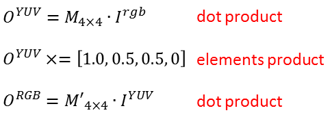

This way, SSE calculations can be easily performed. Note that every pixel, now, is represented with 16 bytes (we saved R, G, and B elements in sse_subpixel_blocks_optimization as 4-byte values), and with each dot product (using one of XMM registers), we are able to calculate one pixel.
The SSE optimized assembly code for such a transformation would be:
.DATA
ALIGN 16
M_matrix_row_0 real4 0.299, 0.587, 0.114, 0.0
M_matrix_row_1 real4 -0.1471, -0.2888, 0.436, 0.0
M_matrix_row_2 real4 0.615, -0.5149, -0.10001, 0.0
M_matrix_row_3 real4 0.0, 0.0, 0.0, 0.0
M_prime_matrix_row_0 real4 1.0, 0.0, 1.13983, 0.0
M_prime_matrix_row_1 real4 1.0, -0.39465, -0.5806, 0.0
M_prime_matrix_row_2 real4 1.0, 2.03211, 0.0, 0.0
M_prime_matrix_row_3 real4 0.0, 0.0, 0.0, 0.0
element_product real4 1.0, 0.5, 0.5, 0.0
_PSHUF_PATTERN_1 DWORD 1,1,0,1
_PSHUF_PATTERN_2 DWORD 1,0,1,1
CODE SEGMENT DWORD PUBLIC 'CODE' USE32 ASSUME CS:CODE
_sse_rgb_yuv_rgb PROC NEAR
push ebp
mov ebp, esp
mov eax, DWORD PTR[ebp + 8]
mov ebx, DWORD PTR[ebp + 12]
xorps xmm6, xmm6
movaps xmm0, XMMWORD PTR[M_matrix_row_0]
movaps xmm1, XMMWORD PTR[M_matrix_row_1]
movaps xmm2, XMMWORD PTR[M_matrix_row_2]
movaps xmm4, XMMWORD PTR[eax]
movaps xmm5, XMMWORD PTR[ebx]
mulps xmm0, xmm5
mulps xmm1, xmm5
mulps xmm2, xmm5
haddps xmm0, xmm6
haddps xmm0, xmm6
haddps xmm1, xmm6
haddps xmm1, xmm6
haddps xmm2, xmm6
haddps xmm2, xmm6
pshufd xmm1, XMMWORD PTR[_PSHUF_PATTERN_1]
pshufd xmm2, XMMWORD PTR[_PSHUF_PATTERN_2]
addps xmm0, xmm1
addps xmm0, xmm2
movaps xmm4, xmm0
mulps xmm4, XMMWORD PTR[element_product]
movaps xmm0, XMMWORD PTR[M_prime_matrix_row_0]
movaps xmm1, XMMWORD PTR[M_prime_matrix_row_1]
movaps xmm2, XMMWORD PTR[M_prime_matrix_row_2]
mulps xmm0, xmm4
mulps xmm1, xmm4
mulps xmm2, xmm4
haddps xmm0, xmm6
haddps xmm0, xmm6
haddps xmm1, xmm6
haddps xmm1, xmm6
haddps xmm2, xmm6
haddps xmm2, xmm6
pshufd xmm1, XMMWORD PTR[_PSHUF_PATTERN_1]
pshufd xmm2, XMMWORD PTR[_PSHUF_PATTERN_2]
addps xmm0, xmm1
addps xmm0, xmm2
movaps [ebx], xmm0
mov esp, ebp
pop ebp
ret
_sse_rgb_yuv_rgb ENDP
and in C code:
extern void sse_rgb_yuv_rgb(void* yuv, void* rgb);
float* rgb = ;
float* yuv = ;
unsigned int counter = 0;
for(counter = 0; counter < number_of_elements; counter++)
sse_rgb_yuv_rgb(&yuv[counter], &rgb[counter]);
This member has not yet provided a Biography. Assume it's interesting and varied, and probably something to do with programming.


 General
  News
News  Suggestion
  Question
  Bug
Bug  Answer
  Joke
Joke  Praise
  Rant
Rant  Admin
Admin 


