Introduction
While this article ultimately covers creating a color wheel, the alternative method presented for filling in a circle could prove quite useful for a wide array of applications. The algorithm presented is built for speed. The coordinate mapping process is covered first; coloring the wheel is examined second.
The End Product
The sample color wheel shown below is from Blender 2.80. The general concept is nothing new; it can be found on every platform in any number of apps. This article explains how to program an app to generate a color wheel on the fly – not at the HTML-ish level, where huge amounts of processing time are wasted by drawing pixels that will eventually be masked off, but through precision processing that ensures no pixel is missed, no pixel is drawn twice, and no pixel is ever drawn that is not part of the final display. Accuracy is as near 100% as the CPU’s SSE instructions will allow.
The process involves multiple steps, but as these steps are laid out, full explanations are given as to what is happening; who’s doing what and why.
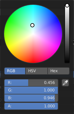
Figure 1. Blender 2.80 Color Wheel
This article only covers generation of the color wheel itself and an attendant intensity slider; the remainder of the controls are up to the developer and are not covered here.
Mapping Process Overview
If radial lines are used to generate the wheel (the filled-in circle) by incrementally stepping around the circumference of the circle, blank pixels will very likely be left somewhere inside the fill area, unless angles of less than one degree are used. In a test implementation, I had to reduce angular movement to 0.2 degrees per step before all pixels were colored (save for four pixels each one-off from the center). This, of course, resulted in a ton of redundant processing, coloring the same pixels multiple times with the problem worsening as the center was approached. Bresenham’s line and/or midpoint circle algorithms deliver the same errors if concentric circles are to be generated for the fill effect. These algorithms are fine for creating a single circle consisting only of a line, but in this implementation, every pixel inside the circle must be filled in, and no two pixels are identical in color.
If you want to see the problem up close and personal, simply go into Windows Paint or any other app that lets you draw circles. Draw some concentric circles, one inside the other, and you’ll begin to see the blank pixels proliferate; orphans that no circle of any diameter claimed.
I set out to find a way of eliminating the redundancy while taking care of the orphaned pixel problem. The task was daunting at best, and I spent many days in intensive analysis trying to figure out a method for doing it fast and reliably. Eventually, I came up with the method presented here.
The method this article explains is so basic and simple conceptually that it’s almost embarrassing. There is light trigonometry involved; this is to be expected when you’re dealing with circles. But the bulk of the processing is all about directly addressing selected pixels instead of constantly overamping the CPU by asking “where am I now?”
Figure 2 below shows the basic concept of working with pixels instead of points on the circle.

Figure 2. Pixel-Based Representation of a Circle
Delimiting the Rows
The mapping algorithm processes horizontal runs of pixels from the far left to the far right of the circle, beginning with y = radius - 1 and stepping down by y-- each iteration, up to but not including the center pixel where y = 0. Actual calculations are done for the upper right quadrant only. Each row is then processed as a single run – always guaranteed to be a straight line parallel to the X axis – from -x to x, then y is negated and the process repeats for the same line on the lower half of the circle.
A separate function is called to process each row.
Determining Row Start and End Points
Negate an end point and you have the start point, so only one point needs to be located. Given any value for y, the value for x will be the point where a pixel intersects the outer circle. The y coordinate will always be an even whole number, and for each y, the corresponding x needs to be calculated. This is done with the very simple equation:
X = sqrt ( ( radius ^ 2 ) – ( y ^ 2 ) )
Once x is known, the entire row at y is ready to process from -x to x. Negate y and process the row again; this covers the lower half of the circle. Running this process through for every value of y from ( radius – 1) to 1 fills in the entire circle except for a single row along the X axis. This is processed “manually,” as here x will be equal to radius. For this row, send in y = 0 and x = radius to the processing function.
Coloring the Pixels
If you’re not creating a color wheel, the next section won’t be of much use to you. The code for mapping the circle is covered in part 2.
By definition, every pixel in a color wheel in a color wheel is unique. Therefore, the color of every pixel must be set separately. While I haven’t delved into making the attempt, it stands to reason that if some kind of ongoing tracking were attempted, to incrementally color each pixel in a row based on some progressive pattern, the curve of the circle would have to be offset to do this. The resulting code would likely cost more than it would return. Determining the color for each pixel is quite simple, but it should be noted that from this point forward, virtual radial lines are used to set the required colors because that’s how the wheel progresses in its tinting.
Color Progression
Colors follow the colors of the rainbow: red, orange, yellow, green, blue, indigo, and violet. Figure 3 below illustrates the distribution of the rainbow spectrum across 7 equal sections of arc around the circle.
Figure 3. Color Distribution of the Rainbow Spectrum
As the distance to the 0, 0 center of the circle closes, each component of the pixel’s base color (discussed next) is shifted the same % toward white as the pixel is toward the center point. If a pixel is 43% of the way from the outer periphery of the circle to the center point, then each component of that pixel (red, green, and blue) move 43% of the way to solid white.
Everybody Has an Angle
Every pixel has an x and a y coordinate. This is all that’s needed to determine the angle of a line running from the center point 0, 0 to the pixel in question. Simply plug x and y into the standard arctangent equation:
angle = atan ( x / y )
The equation is simplified because the center point is always at 0, 0.
A brief spasm of true ugliness is encountered here: SSE won’t give up an arctangent. Why is anybody’s guess, but the situation is what it is and therefore requires falling back on the ancient FPU. The code for that foray is included in the overall code dissection in part 2 of this article.
With the angle known, processing can continue, to determine which “slice” of the circle the pixel falls inside. Each slice is (360 / 7) degrees of arc, or 51.428571… degrees. The result of dividing the angle by (360/7) is split into two values, both of which are needed. The integer quotient is the index of the slice, from 0 to 6. The remainder gives the % of the way through the slice the angle is situated. A virtual line might cut through slice index 2, 38% of the way from the start of slice 2 to the start of slice 3.
I created a lookup table declaring the starting colors for the beginning of each pie slice. The table has 8 entries for 7 slices, because entry [index] holds the starting color, and entry [index+1] holds the ending color. The inclusion of the 8th entry, which is simply a repeat of entry 0, eliminates the requirement for costly wrapping of the pointer back to the start of the table to find the end color in the case of slice index 6.
The table is shown below; this table is included as-is (value-wise) in my own code:
CValues     dword     00FF0000h, 00FF8000h, 00FFFF00h, 0000FF00h
            dword     000000FFh, 008000FFh, 00FF00FFh, 00FF0000h
A Lighter Shade of White
Working through a sample pixel located at 105, 79 in a color wheel with a radius of 175:
First, get the angle:
angle = atan ( x / y ) = atan ( 105 / 79 ) = 89.5670288352
Divide the angle by 51.428571 degrees per slice:
slice_index = int ( 89.5670288352 / 51.428571) = 1
The remainder of the same equation gives the percent of the distance across the slice:
slice_percent = 89.5670288352 % 51.428571 = .741581
With slice_index = 1, the start of the color range from the lookup table is entry[1] and the end is entry[1+1].
start_color = table [ 1 ] = 0x00FF8000
end_color   = table [ 2 ] = 0x0FFFF00
The distance across this slice must be broken up into components:
red component start   = 0xFF8000
green component start = 0xFF8000
blue component start  = 0xFF8000

red component end     = 0xFFFF00
green component end   = 0xFFFF00
blue component end    = 0xFFFF00
Next, calculate the span of each component by subtracting start from end:
red span   = red end – red start     = 0xFF – 0xFF = 0
green span = green end – green start = 0xFF – 0x80 = 0x7F
blue span  = blue end – blue start   = 0x00 – 0x00 = 0x00
Finally, each span is multiplied by slice_percent then added to the start color, always rounding to the nearest whole number:
red_final   = red start + ( red_span * slice_percent )
            = 0xFF + ( 0 * .741581 ) = 0xFF
green_final = green_start + ( green_span * slice_percent)
            = 0x80 + ( 0x7F * .741581 ) = 0xDE
blue final  = blue_start + ( blue span * slice_percent )
            = 0x00 + ( 0x00 * .741581 ) = 0x00
The final base color value is 0x[red][green][blue] or 0xFFDE00.
The last step is to shift this value toward white. The coordinates are 105, 79; using the Pythagorean theorem, the distance from the center point 0, 0, is:
sqrt ( ( x ^ 2 ) + ( y ^ 2 ) ) = sqrt ( ( 105 ^ 2 ) + ( 79 ^ 2 )
                               = 131 (rounded to nearest whole #)
The radius of the sample wheel radius is 175, so divide the pixel’s distance from the center by the radius:
shift_percent = 131 / 175 = 0.748571
This means shifting each component .748571 of the way between the base color and 0xFFFFFF.
red start   = 0xFFDE00
green start = 0xFFDE00
blue start  = 0xFFDE00
The span for each component is obtained by subtracting the component from 0xFF, since all comonents are 0xFF for white:
red span   = 0xFF – 0xFF = 0x00
green span = 0xFF – 0xDE = 0x21
blue span  = 0xFF – 0x00 = 0xFF
The end color, always pure white, is 0xFF for all components. Each span is multiplied by .748571, the % of the distance for the target pixel from the outer periphery of the circle (the radius) to the center at 0, 0, then added to the base color. This gives the amount of movement toward pure white:
red_final   = red start + ( red_span * shift_percent )    = 0xFF + ( 0x00 * .741581 ) = 0xFF
green_final = green_start + ( green_span * shift_percent) = 0xDE + ( 0x21 * .741581 ) = 0x18
blue_final  = blue start + ( blue_span * shift_percent)   = 0x00 + ( 0xFF * .741581 ) = 0xBD
The final color for the pixel, taking into account rotation across the 7 slices of the rainbow spectrum, then shifting toward white at the center of the wheel, is 0xFF18BD.
A sample of the actual output from this system is shown in Figure 4. The black “cross hairs” are the “picker” that selects the current color. This is overlaid on the color wheel.
Figure 4. Actual Output
The color red being at the bottom of the wheel is the result of the way I’m manually storing pixel values directly to the bitmap data on a bottom-up bitmap (something this article will NOT be using; why I do it defies explanation).
Storing Pixel Data
A final word on setting color data, before diving into the actual code: I personally always use the Windows API call CreateDIBSection to create a 32-bit bitmap for all my bitmaps, and the color wheel is no exception. It can be selected into a device context and blitted the same as a 24-bit bitmap, and it has the added benefit of storing the alpha channel for the times when that’s needed. The main reason behind my choice is that 24-bit bitmaps are stored in memory with padding at the end of each display row for alignment. 3-byte entries per pixel just don’t work well with a coordinate system and require what I consider to be too much extra work (on the part of both the developer and the CPU, if writing pixel data is done directly) to save that extra byte of data per pixel, and the padding confuses things even more. 32-bit bitmaps are stored with no padding and have nice, even dword entries per pixel. Locating the target write position is tricky at first, if you create the default bottom-up bitmap (we won’t be doing that here; it confuses things and if you read up on the history of why bottom-up bitmaps exist at all, the decision to create them was really pretty ludicrous).
Another reason for using CreateDIBSection held true at one time; I’m unsure of whether or not Microsoft has changed where compatible bitmaps are stored in or prior to Windows 10. I’ve made efforts to find out but so far I’ve been unable to locate a definitive answer. The idea is that at least in the past, Windows stored compatible bitmaps (DDBs or Device Dependent Bitmaps), created with the CreateCompatibleBitmap function, in system memory, which was much too limited for the task. I’ve hit the wall before where there was insufficient memory to create a compatible bitmap and that’s when I moved to DIBs or Device Independent Bitmaps. DIBs are stored outside system memory so you’re unlikely to ever run out of whatever memory is used.
All things considered, I see little if any reason to use CreateCompatibleBitmap. When CreateDIBSection is used, simply specify a negative height to make the bitmap top-down, which is how most sane people would prefer it, and a variable is passed to the function that receives a pointer to the bitmap data. The only special requirement is that GdiFlush is called before writing directly to the bitmap data, to ensure the system is not in the process of writing to it simultaneously.
Next In Line…
Part 2 of this article is all about the actual code. If you’re following this work in real time, it will take a little time to make it all presentable. If there’s one thing I can’t stand, it’s sample code that is flawed. I refuse to jump into that arena. From formatting to actual debugging, the sample code provided must be gone over painstakingly and with a fine tooth comb to ensure there are no errors in it.
Discussion of the code for implementing the process contained in this article is in-depth and quite complete. Everything from initializing the process to displaying the bitmap is covered. At the end of part 2, you are unlikely to have any major gaps in your understanding of why things were done the way they were, as well as what each instruction is actually doing.
Be aware that the magic of SSE takes a large chunk of tedium and complexity out of the process of coloring pixel data because of its ability to process all three color channels (components) simultaneously. The entire process works on 3 components as if they were one, and this goes a very long way toward simplifying the code and speeding up development, as well as eliminating bugs.
Part 2 en route…
History
- 18th May, 2019: Initial version
I work as a contract developer, specializing in assembly language driver software for specialized hardware. I also focus on identifying and removing performance bottlenecks in any software, using assembly language modifications, as well as locating hard-to-find bugs. I’m a specialist; I prefer to stay away from everyday, mundane development. I can fix problems in high level languages but as a rule I don’t like working with them for general development. There is no shortage of experienced developers in any language besides assembly. I am very much a niche programmer, a troubleshooter; the closer to the hardware I work, the happier I am. I typically take on the tasks others can’t or don’t want to do.


 General
  News
News  Suggestion
  Question
  Bug
Bug  Answer
  Joke
Joke  Praise
  Rant
Rant  Admin
Admin 


