Introduction
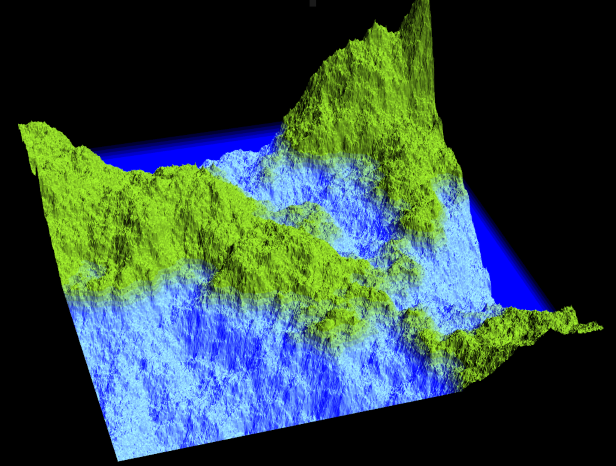
This article is intended for all those people who want to approach the 3D visualization in WPF. Instead of just displaying the classic simple square / triangle, we will represent a simple 2D map in a 3D environment.
Background
For basic information regarding 3D graphics in WPF, please refer to this very useful and easy explanation.
For the map generation, I will use an algorithm very well explained here.
Using the Code
My sample is made up of two files:
terrainGenerator.cs
Which contain the map generator to create the Heightmap.
In computer graphics, a heightmap or heightfield is a raster image used to store values, such as surface elevation data, for display in 3D computer graphics. For more information, check out this link.
The code is a partial port of the code from here.
Quote:
The algorithm
Here's the idea: take a flat square. Split it into four sub-squares, and move their center points up or down by a random offset. Split each of those into more sub-squares and repeat, each time reducing the range of the random offset so that the first choices matter most while the later choices provide smaller details.
That's the midpoint displacement algorithm. Our diamond-square algorithm is based on similar principles but generates more natural-looking results. Instead of just dividing into sub-squares, it alternates between dividing into sub-squares and dividing into sub-diamonds.
If you have time, please visit the site, the algorithm is really very well explained. It will also go further in explaining a 2D rendering with pseudo lighting effect.
Here, I will give you a short explanation:

- We set manually the four starting corners of the terrain height map (see "image 1").
- We find the height map value of the center of the square by averaging the corner point plus a random value (see "image 2").
- We trace a diamond and we find the height map value of the corners by averaging its diamond neighbours (see "image 3").
- Now we can divide the resulting image into sub-square, and if the size is greater than 1 pixel, we go back to point 2.
MainWindow.cs
This contains the main controls but also the 3D representation part. When the user clicks on the generate button (_GenerateTerrainButtonClick):
- Generation of the terrain
heightmap:
...
TerrainGenerator tg = new TerrainGenerator(detailValue);
tg.Generate(roughnessValue);
...
Detail value indicates the level of detail of the map, more detail will result in a bigger map created. Default value is set to 9 (which results in a 513x513 map). The Map is a two dimensional array of float. Each dimension of the array is calculated as:
...
_Size = (int)(Math.Pow(2, detail) + 1);
_Map = new float[_Size,_Size];
...
roughnessValue determines whether the terrain is smooth (values near zero) or mountainous (values near one). Default value is set to 0.3.
- Calculation of the minimum and maximum of the
heightmap:
Calculates the minimum and maximum value of the heightmap to visualize the map correctly centered.
- 3D visualization:
In my code, the XAML file contains:
<Viewport3D Name="_MyViewport3D">
    <Viewport3D.Camera>
        <PerspectiveCamera x:Name = "_MainPerspectiveCamera"
         Position = "0 0 2048" LookDirection = "0 0 -1" />
    </Viewport3D.Camera>
    <ModelVisual3D>
        <ModelVisual3D.Content>
            <Model3DGroup x:Name="_MyModel3DGroup">
            </Model3DGroup>
        </ModelVisual3D.Content>
    </ModelVisual3D>
</Viewport3D>
Viewport3D is a component that renders the contained 3-D content within the 2-D layout bounds of the Viewport3D element. It will contain all the elements that we need to represent our 3D scene:
-
A camera like in a film. A 3-D scene, like in the real world, looks different depending on the point of view. The Camera class allows you to specify this point of view for a 3-D scene by setting the correct Position and LookDirection variable.
There are different types of camera:
Quote:
The ProjectionCamera allows you to specify different projections and their properties to change how the onlooker sees 3-D models. A PerspectiveCamera specifies a projection that foreshortens the scene. In other words, the PerspectiveCamera provides vanishing-point perspective. You can specify the position of the camera in the coordinate space of the scene, the direction and field of view for the camera, and a vector that defines the direction of "up" in the scene.
https://docs.microsoft.com/en-us/dotnet/framework/wpf/graphics-multimedia/3-d-graphics-overview
-
A light to illuminate the scene. Light in 3-D graphics does what lights do in the real world: they make surfaces visible.
There are different type of lights:
Quote:
- AmbientLight: Provides ambient lighting that illuminates all objects uniformly regardless of their location or orientation.
- DirectionalLight: Illuminates like a distant light source. Directional lights have a Direction specified as a Vector3D, but no specified location.
- PointLight: Illuminates like a nearby light source. PointLights have a position and cast light from that position. Objects in the scene are illuminated depending on their position and distance with respect to the light. PointLightBase exposes a Range property, which determines a distance beyond which models will not be illuminated by the light. PointLight also exposes attenuation properties which determine how the light's intensity diminishes over distance. You can specify constant, linear, or quadratic interpolations for the light's attenuation.
- SpotLight: Inherits from PointLight. Spotlights illuminate like PointLight and have both position and direction. They project light in a cone-shaped area set by InnerConeAngle and OuterConeAngle properties, specified in degrees.
https://docs.microsoft.com/en-us/dotnet/framework/wpf/graphics-multimedia/3-d-graphics-overview
In my code, I add the light in code because I want to put it in a specific position related to the size of the map.
...
PointLight pointLight = new PointLight
(Colors.White, new Point3D(tg.Size / 2, tg.Size / 2, tg.Size * 3 / 5));
...
Light can be applied globally (as in the real world) by adding them to the Viewport3D or to a specific object/group of object to obtain some special effect.
-
The 3D object to represent.
Basically, any surface structure can be represented as a bunch of triangles. The triangle is the most atomic and primitive geometry.
Currently, the WPF supports 3D geometries with GeometryModel3D.
Quote:
To build a model, begin by building a primitive, or mesh. A 3-D primitive is a collection of vertices that form a single 3-D entity. Most 3-D systems provide primitives modeled on the simplest closed figure: a triangle defined by three vertices. Because the three points of a triangle are coplanar, you can continue adding triangles in order to model more complex shapes, called meshes.
The WPF 3-D system currently provides the MeshGeometry3D class, which allows you to specify any geometry; it does not currently support predefined 3-D primitives like spheres and cubic forms. Begin creating a MeshGeometry3D by specifying a list of triangle vertices as its Positions property. Each vertex is specified as a Point3D. (In Extensible Application Markup Language (XAML), specify this property as a list of numbers grouped in threes that represent the coordinates of each vertex.) Depending on its geometry, your mesh might be composed of many triangles, some of which share the same corners (vertices). To draw the mesh correctly, the WPF needs information about which vertices are shared by which triangles. You provide this information by specifying a list of triangle indices with the TriangleIndices property. This list specifies the order in which the points specified in the Positions list will determine a triangle.
https://docs.microsoft.com/en-us/dotnet/framework/wpf/graphics-multimedia/3-d-graphics-overview
For each object in our world, we can also define the Material of which the object is made of. The light will interact with the material properties according to the material specification:
Quote:
To define the characteristics of a model's surface, WPF uses the Material abstract class. The concrete subclasses of Material determine some of the appearance characteristics of the model's surface, and each also provides a Brush property to which you can pass a SolidColorBrush, TileBrush, or VisualBrush.
-
DiffuseMaterial specifies that the brush will be applied to the model as though that model were lit diffusely. Using DiffuseMaterial most resembles using brushes directly on 2-D models; model surfaces do not reflect light as though shiny.
-
SpecularMaterial specifies that the brush will be applied to the model as though the model's surface were hard or shiny, capable of reflecting highlights. You can set the degree to which the texture will suggest this reflective quality, or "shine," by specifying a value for the SpecularPower property.
-
EmissiveMaterial allows you to specify that the texture will be applied as though the model were emitting light equal to the color of the brush. This does not make the model a light; however, it will participate differently in shadowing than it would if textured with DiffuseMaterial or SpecularMaterial.
https://docs.microsoft.com/en-us/dotnet/framework/wpf/graphics-multimedia/3-d-graphics-overview
After this little explanation, I can go back with the explanation of the code, to generate the terrain I perform 3 pass:
-
Design the terrain.
For the terrain, I will use a DiffuseMaterial with a uniform LimeGreen color applied.
I will go through my generated map to create a collection of Point3d where I set X and Y from the map coordinates, while for the Z coordinate, I will use the value of the heightmap relative to the heightmap minimum and maximum value.
((MeshGeometry3D)myTerrainGeometryModel.Geometry).Positions = point3DCollection;
All these points will be joined by using triangles.
To perform this operation, we must indicate which 3D point we must use to generate triangle. We can do this by creating a collection of indexes.
((MeshGeometry3D)myTerrainGeometryModel.Geometry).TriangleIndices =
                                                      triangleIndices;
Every entry in this collection is an index in the Position list.
Every triple of indexes in this list represents a triangle. For a triangle in a given 3-D mesh, the order in which the triangle's vertex positions are specified determines whether the triangle face is a front or back face.The WPF 3-D implementation uses a counter-clockwise winding order; that is, the points that determine a front-facing mesh triangle's positions should be specified in counterclockwise order, as viewed from the front of the mesh.
private void _DrawTerrain(float[,] terrainMap, int terrainSize, float minHeightValue, float maxHeightValue)
{
float halfSize = terrainSize / 2;
float halfheight = (maxHeightValue - minHeightValue) / 2;
GeometryModel3D myTerrainGeometryModel = new GeometryModel3D
(new MeshGeometry3D(), new DiffuseMaterial(new SolidColorBrush(Colors.GreenYellow)));
Point3DCollection point3DCollection = new Point3DCollection();
Int32Collection triangleIndices = new Int32Collection();
for (var y = posY; y < maxPosY; y++) {
for (var x = posX; x < maxPosX; x++) {
point3DCollection.Add(new Point3D(x - halfSize, y - halfSize, terrainMap[x, y] - halfheight));
}
}
((MeshGeometry3D)myTerrainGeometryModel.Geometry).Positions = point3DCollection;
int ind1 = 0;
int ind2 = 0;
int xLenght = maxPosX ;
for (var y = posY; y < maxPosY - 1; y++) {
for (var x = posX; x < maxPosX - 1; x++) {
ind1 = x + y * (xLenght);
ind2 = ind1 + (xLenght);
triangleIndices.Add(ind1);
triangleIndices.Add(ind2 + 1);
triangleIndices.Add(ind2);
triangleIndices.Add(ind1);
triangleIndices.Add(ind1 + 1);
triangleIndices.Add(ind2 + 1);
}
}
((MeshGeometry3D)myTerrainGeometryModel.Geometry).TriangleIndices = triangleIndices;
_MyModel3DGroup.Children.Add(myTerrainGeometryModel);
}
-
After designing the terrain, I create some layer to add "water effect" to my world.
To gain a simple but effective water instead of using a 'simple' DiffuseMaterial, I use an EmissiveMaterial with a uniform Blue color with an opacity of 0.2.
I could have used a single square at a certain height to obtain a nice effect, but I preferred to use 10 layers to give a sense of depth to the water.
private void _DrawWater(float[,] terrainMap,
int terrainSize, float minHeightValue, float maxHeightValue, float waterHeightValue)
{
float halfSize = terrainSize / 2;
float halfheight = (maxHeightValue - minHeightValue) / 2;
SolidColorBrush waterSolidColorBrush = new SolidColorBrush(Colors.Blue);
waterSolidColorBrush.Opacity = 0.2;
GeometryModel3D myWaterGeometryModel =
new GeometryModel3D(new MeshGeometry3D(), new EmissiveMaterial(waterSolidColorBrush));
Point3DCollection waterPoint3DCollection = new Point3DCollection();
Int32Collection triangleIndices = new Int32Collection();
int triangleCounter = 0;
float dfMul = 5;
for (int i = 0; i < 10; i++) {
triangleCounter = waterPoint3DCollection.Count;
waterPoint3DCollection.Add(new Point3D(-halfSize, -halfSize, waterHeightValue - i * dfMul - halfheight));
waterPoint3DCollection.Add(new Point3D(+halfSize, +halfSize, waterHeightValue - i * dfMul - halfheight));
waterPoint3DCollection.Add(new Point3D(-halfSize, +halfSize, waterHeightValue - i * dfMul - halfheight));
waterPoint3DCollection.Add(new Point3D(+halfSize, -halfSize, waterHeightValue - i * dfMul - halfheight));
triangleIndices.Add(triangleCounter);
triangleIndices.Add(triangleCounter + 1);
triangleIndices.Add(triangleCounter + 2);
triangleIndices.Add(triangleCounter);
triangleIndices.Add(triangleCounter + 3);
triangleIndices.Add(triangleCounter + 1);
}
((MeshGeometry3D)myWaterGeometryModel.Geometry).Positions = waterPoint3DCollection;
((MeshGeometry3D)myWaterGeometryModel.Geometry).TriangleIndices = triangleIndices;
_MyModel3DGroup.Children.Add(myWaterGeometryModel);
}
-
Now my world is quite complete, but I have to build a containing box in order to hide some part of the object when we rotate it.
The box consists of a simple black wall.
-
3D navigation with mouse interaction:
For 3D navigation, I used the code from here.
Points of Interest
When I approached 3D, I found a very simple and intuitive tutorial that was explaining the very basic knowledge but they did not get me involved. I hope this tutorial will be a bit more funny to understand and use.
This is my very first approach to 3D so if you have any suggestions for modifications, please don't hesitate to contact me.
History
- Version 1.0.0 - July 2017 - First release
- Version 1.0.1 - July 2017 - Limited the details of the map generation to 12, the 3D terrain generation is now divided in cells of maximum dim 4096*4096
- Version 1.0.2 - August 2017 - Optimized point definition, now I don't duplicate point already inserted
- Version 1.0.3 - September 2017 - Optimized the division in cell, now with certain graphic card, we can push the limit of the details to 13
I started programming at Teinos, in a 5 person software working team in march 2004. I got some experience interfacing our main program to various external applications. All of these experiences allowed me to get in touch with many people: end-user, technician and commercial one; learning how to interface myself with these people. After some period I was moved to 'single' software application development. This led me to learn the whole process of software development. From the definition of the specifications to the software release and many times also the installation of the product to the end-user.
In 2009, I moved to ATS. I was charged as Lead Software Developer in a team for a long term new project: Primo (released for the first time in 2010-Q3). The software part for this project was completely written from scratch. These experience led me to understand how to organize the work of a team and take critical decision.
In 2014, in collaboration with a multinational corporation, we started the development of a completely new machine: ARCO FP (released for the first time in 2015-Q3). The software part for this project was completely written from scratch. This experience teaches me how to integrate our company with the needs and rules of other company and how to mitigate different approaches to the production phases.


 General
  News
News  Suggestion
  Question
  Bug
Bug  Answer
  Joke
Joke  Praise
  Rant
Rant  Admin
Admin 


 .
.