Introduction
In this tutorial, we will try to discuss the basic transformation in DirectX. We will discuss only the world transform because it’s the simplest transform, but honestly I should say it’s a complicated subject, especially if you tried to understand the underlying concepts of transformation, then you will be lost in pure math problems.
So, I will not discuss the mathematical concepts of vectors and matrices (because I don’t understand it myself!) but we learn how to use them for transformation.
Background
This tutorial is a continuation of my previous tutorial, “Starting Directx using Visual Basic” so I assume you already understand how to create a DirectX device.
Draw a Square
“Download incomplete_project and start working on it.”
Firstly, we will draw a square before transforming it. Declare this variable in your class:
Dim buffer As VertexBuffer
In creat_vertxbuffer Sub, write:
Sub creat_vertxbuffer()
buffer = New VertexBuffer(GetType(CustomVertex.PositionColored), 4, device, _
Usage.None, CustomVertex.PositionColored.Format, Pool.Managed)
Dim ver(3) As CustomVertex.PositionColored
ver(0) = New CustomVertex.PositionColored(-0.5F, -0.5F, 0, Color.Red.ToArgb)
ver(1) = New CustomVertex.PositionColored(-0.5F, 0.5F, 0, Color.Green.ToArgb)
ver(2) = New CustomVertex.PositionColored(0.5F, -0.5F, 0, Color.Blue.ToArgb)
ver(3) = New CustomVertex.PositionColored(0.5F, 0.5F, 0, Color.Yellow.ToArgb)
buffer.SetData(ver, 0, LockFlags.None)
buffer.Unlock()
End Sub
Here, we used PositionColored type in our vertices unlike the previous tutorial where we used TransformedColored type, because we want to apply transform on it. We also used 4 vertices to draw a square.
But the question is: according to what do I determine the position of my vertices? I think you wondered about this position data. What is this (0.5) and (-0.5) ? and you could say: in the previous tutorial, the matter is clear we drew directly according to the screen coordinate (0,0 point in the upper left corner), but that is exactly the difference! We don’t draw according to the screen coordinate, we draw according to Viewport coordinate.
Viewport
The view port is a rectangle where DirectX projects (not draw) the scenes, you can consider the view port as window open into scenes, see below:
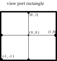
So the max X value in viewport is 1 and the minimum is -1 the same as Y, but what about the 3rd dimension Z? Where is it?! And what are its min max values?
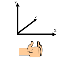
To know the positive direction of Z axis in Direct3d, we use the left hand rule:
If your left hand points toward the positive direction of X axis and your fingers points toward the positive direction of Y axis, then the positive direction of Z axis is the direction of your thumb as in the picture shown below:
And the min max value of Z is determined by you:
Viewport.MinZ() as single
Viewport.MaxZ() as single
But the default values are MinZ =0 and MaxZ=1. Any value outside this range will be clipped (and this is another subject!) but we will ignore the Z axis completely in this tutorial for simplification purposes.
We can set viewport for the device using:
device.Viewport = ourViewport
Moreover, we can use more than one view port in our scenes; for now we will use the default view port which is the size of screen.
Another important thing is that the viewport dimension does not change with screen dimension or width height ratio of screen, meaning that it does not matter whether your form is oblong or square, and in any case the (-1,-1) point is in the lower left corner and (1,1) point is in the upper right corner of your viewport.
The Main Loop
I think after the above explanation, you have imagined the position of the square, but you want to see, not imagine! OK, a little more code and you can see what we have done. Unlike the previous tutorial, we need here a main loop because we have to call the drawing routine repeatedly, so we put it all in a loop as here:
initilizdx()
creat_vertxbuffer()
Me.Show()
Do While Me.Created
transform()
draw_me()
Application.DoEvents()
Loop
End
Application.DoEvents is a very important procedure in this infinite loop. It lets the program process all system messages and return to the loop, if you did not use it, your program will not respond to any message (closing for example).
Put the above code block in <code>LoadForm Event and write draw_me Sub:
Sub draw_me()
    device.Clear(ClearFlags.Target, Color.Black, 0, 0)
    device.BeginScene()
    device.VertexFormat = CustomVertex.PositionColored.Format
    device.SetStreamSource(0, buffer, 0)
    device.DrawPrimitives(PrimitiveType.TriangleStrip, 0, 2)
    device.EndScene()
    device.Present()
End Sub
This is slightly different from the previous tutorial because we used TriangleStrip in primitive type, don’t worry I will explain, now hit F5 and see the result.
A beautiful colorful square!
So what is TriangleStripe? The TriangleStripe method forms a triangle from the last three vertices. If you want 2 triangles, you should use 4 vertices as we did, and for 3 triangles use 5 vertices:
Triangle1(ver1,ver2,ver3),triangle2(ver2,ver3,ver4),triangle3 (ver3,ver4,ver5)…
When Ver = vertex
In other words, the triangle uses the last side of previous triangle, resulting in shared side in any consecutive triangles.
As a better practice, you should put a timer in your loop, but for now we write it without timer to be simple.
But where is the transformation? We have learned how to draw squares and triangles from the previous tutorial and now want to move it around. Don’t worry, we will learn how to do so, but firstly you should know the primary tool of transformation, Matrix.
Note: If you are not interested in theories, skip these following sections and go ahead to the (Practical) section.
Matrix
This is the source of panic for any beginner of graphics and 3D programming, and it’s really hard to understand. Most of the tutorials on the internet don't explain the concepts of matrix and (specially) matrix multiplication. They says: this matrix, and this how to use it, and don’t ask any questions!. And I will not be an exception!
As we know, matrix is a rectangular layout of numbers in the form of rows and columns, an m x n matrix is a matrix that has m rows and n columns, the element of matrix is named by the number of its row and the number of its column, for example A2,3 means the element of A matrix in the 2nd row and 3rd column.

In the above A matrix: A1,1 =2 , A3,1 =12 , A2,3 = 54.
In 3D transformation, we use 4X4 matrix to represent the system coordinates and we call it transformation matrix. If we want to transform our scenes, we should multiply each vertex by the transformation matrix, also we can transform our matrix by another matrix which results in cooperation effect.
In other words, if you multiply matrix that rotates around X axis by a matrix that rotates around Y axis, the result is a matrix that rotates around X axis, then around y axis. If you invert the operation, the result is a matrix that rotates around Y axis then around X axis, because matrix multiplication is not commutative.
But how is matrix multiplication done? In practice, you don’t need to know how to multiply matrix manually. You can simply use (*) operator to do so (only in managed directx) or you can use Matrix. Multiply () function which is a shared Sub in Matrix class, but if you resolved to understanding how to multiply matrix, you can search through the net or content by the brief description below.
If A , B are matrices, then A X B is valid only if the number of columns in A = the number of rows in B, the resulting matrix has the number of rows of A and the number of columns of B.
The resulting matrix calculated by multiplication each row in A by each column in B (better to say multiply matrix A by each column vector in B) as in the picture below:
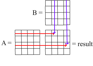
As in the picture, the result of multiply row 1 by column 2 is a number and it is stored in element1,2 in result matrix. Guess which element bears the result of row 3 * column 4?
And here is how we multiply row by column:

Didn’t understand? No problem. As I said above, you don’t need to understand matrix multiplication because you can do it simply by * operator!, A*B = result.
Returning to our subject, how to use this matrix in transformation, firstly we should know how to represent the world coordinate in a matrix.
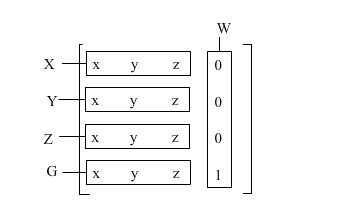
This 4x4 matrix which is used in transformation:
- X oblong represents the vector of X axis which normally is (1, 0, 0)
- Y oblong represents the vector of y axis which normally is (0, 1, 0)
- Z oblong represents the vector of Z axis which normally is (0, 0, 1)
- And G oblong represents the origin point which normally is (0, 0, 0)
- The W oblong isn't useful in world transformation.
If we applied these values in an 4x4 matrix:
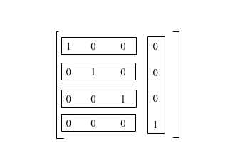
This matrix is called identity matrix because it’s identical to the coordinate system, which means that any vertex or matrix transformed by this matrix will not change.
You may wonder how we can multiply 3 elements vector by this 4x4 matrix?! If you want to multiply it manually, you have to use 4 elements vector (x,y,z,1), but if you used Directx transformation (it’s the best), you don’t need to worry about this.
Translation
The simplest transform in which we change the origin point only:
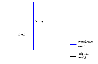
As you see, to build a translation matrix, you only change the point of origin like this:

Replace (x, y, z) by your translation offset values.
To do it by code, declare MatWorld as Matrix in your form class:
Dim MatWorld As Matrix
In sub transform, write this:
Sub transform()
MatWorld = Matrix.Identity
MatWorld.M41 = 0.5
MatWorld.M42 = 0.5
device.Transform.World = MatWorld
End Sub
Before hitting F5, can you imagine the result? As you notice, we changed only the values we want (M41,M42) and left the rest as the identity matrix. The previous code builds the following matrix:
And directx will transform each vertex by this world Matrix.
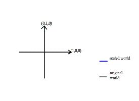
Scaling
To build a scaling matrix, you should determine firstly which axes you want to scale, here we will scale both in y and x axes:
To do so by code, rewrite transform sub as this:
Sub transform()
MatWorld = Matrix.Identity
MatWorld.M11 = 0.5
MatWorld.M22 = 0.5
device.Transform.World = MatWorld
End Sub
Because our square is big, we scaled it to half. Press F5.
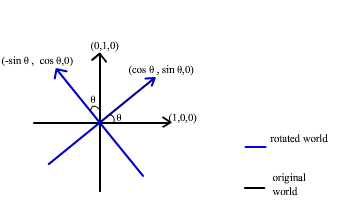
Rotation
Rotation is more complicated than the previous transform (especially in 3D). As I mentioned earlier we will ignore the Z axis, so our rotation should be around Z axis to avoid any change in Z values. To build a rotation matrix around Z axis by angle ?:
To do so by code, rewrite transform sub as follows:
Sub transform()
MatWorld = Matrix.Identity
MatWorld.M11 = Math.Cos(Math.PI / 4) : MatWorld.M12 = Math.Sin(Math.PI / 4)
MatWorld.M21 = -Math.Sin(Math.PI / 4) : MatWorld.M22 = Math.Cos(Math.PI / 4)
device.Transform.World = MatWorld
End Sub
This code builds a matrix that rotates around z axis by 45 degree. This is the matrix we have built:
| Cos(p/4) | sin(p /4) | 0 | 0 |
| -sin(p/4) | cos(p/4) | 0 | 0 |
| 0 | 0 | 1 | 0 |
| 0 | 0 | 0 | 1 |
Practical
If you didn’t understand the previous sections (or didn’t read them at all), no problem, because we usually use matrix functions that come with Direct3D to build transform matrices. Here's how to build a rotation matrix:
Sub transform()
MatWorld = Matrix.Identity
MatWorld.RotateZ(Math.PI / 4)
device.Transform.World = MatWorld
End Sub
Very easy!
You can use other matrix functions:
MatWorld.Translate()
MatWorld.Scale()
MatWorld.RotateX()
MatWorld.RotateY()
Q & A
Q: How I can rotate an object around itself away from the origin point?
A: The best practice is to draw your objects in origin point, rotate them and then translate them to their positions, like this example:
Dim matrix2 As Matrix
Sub transform()
MatWorld.RotateZ(Math.PI / 4)
matrix2.Translate(0.5, 0.5, 0)
MatWorld = MatWorld * matrix2
device.Transform.World = MatWorld
End Sub
Q: What will happen if I wrote matrix2 * MatWorld instead?
A: Matworld * matrix2 means rotate, then translate, but matrix2* MatWorld means translate, then rotate.
Q: I want my square keep rotation each frame, how I can do so?
A: You must keep rotating your matrix in each frame, like this:
Dim MatWorld As Matrix = Matrix.Identity
Sub transform()
MatWorld = MatWorld * Matrix.RotationZ(0.01)
matrix2.Translate(0.5, 0.5, 0)
device.Transform.World = MatWorld * matrix2
End Sub
Or you can change your angle each time.
Q: Is it important to make the matrix identity matrix before any operation?
A: No, but when you declare a new matrix, then all its elements are zero, if you multiply new by any other matrix, the result is zero matrix also, so we make it identity before any operation, but if you use Matrix.rotate (for example), this function builds a rotation matrix, not rotate the matrix, so you don’t need to make it identity before using this function.
Q: I want to draw several objects and apply different transformation to each object, how can I do so?
A: Take this example:
First delete transform sub, and apply transformation inside draw_me:
Dim matrix1 As Matrix = Matrix.Identity
Dim matrix2 As Matrix = Matrix.Identity
Dim matrix3 As Matrix = Matrix.Identity
Sub draw_me()
device.Clear(ClearFlags.Target, Color.Black, 0, 0)
device.BeginScene()
device.VertexFormat = CustomVertex.PositionColored.Format
device.SetStreamSource(0, buffer, 0)
matrix2 = matrix2 * Matrix.RotationZ(0.01)
matrix3 = matrix3 * Matrix.RotationZ(-0.01)
matrix1 = Matrix.Translation(0.3, 0.3, 0)
device.Transform.World = matrix2 * matrix1
device.DrawPrimitives(PrimitiveType.TriangleStrip, 0, 2)
matrix1.Translate(-0.3, -0.3, 0)
device.Transform.World = matrix3 * matrix1
device.DrawPrimitives(PrimitiveType.TriangleStrip, 0, 2)
device.EndScene()
device.Present()
End Sub
Q: Why did you ignore the 3rd dimension? I can make all this work using GDI!
A: OK, I have said that we ignored the 3rd dimension for simplification purposes, but there is another reason. As you know, there is no real 3D in directx, because the final picture which rendered in the screen is 2D, in order to simulate this 3D effect, we adjust the projection matrix.
device.Transform.Projection
You should adjust this projection matrix to project the distal objects small and the proximal objects large to simulate the real eye viewing to the real world, but I think it's enough for you to know the basics of transformation, and maybe in future, I can explain to you the other types of transformation.
Conclusion
I have made complete project as an example of all types of transform we have learned.
I hope I have written something useful. Sorry for my bad English! I usually use Google translate in writing, but I did not have internet connection for several days, so I used a mobile dictionary which was horrible!
The world transform is the simplest transform and there is view and projection transform which is more complicated and no beginner cares to understand them. If some people are interested, I can write another tutorial to explain how to use these transforms.
History
- 15th March, 2011: Initial post
This member has not yet provided a Biography. Assume it's interesting and varied, and probably something to do with programming.


 General
  News
News  Suggestion
  Question
  Bug
Bug  Answer
  Joke
Joke  Praise
  Rant
Rant  Admin
Admin 


 I don't Know What I Can Say