Table of Contents
Making a racing game was always a dream for me. And definitely one of the most challenging tasks I've found so far. But fortunately I have WPF by my side, and by now the task was not only accomplished, but in a easy way. Well, maybe not that easy, but the fact is that Windows Presentation Foundation provided all the tools. All the tools. So, I dare say that once you start using WPF, it's hard to give it up.
This article tells the story about the concepts behind the application and the techniques involved. The goal is to make our readers learn something about WPF, or at least, to enjoy the reading and the application.
You can take a glance of the game by clicking the link below:

To use WPF GrandPrix provided with this article, if you already have Visual Studio 2010, that's enough to run the application. If you don't, you can download the following 100% free development tool directly from Microsoft:
For the game, it was used only one racing circuit, "The José Carlos Pace", also known as Interlagos Circuit, in São Paulo, Brazil. I chose this particular circuit not only because I'm Brazilian, but also because the circuit is a good test for driving abilities - it has many curves, where the speed must be very slow, and long, straight parts where you can easily develop the car's maximum speed. So it serves well the purpose of stressing our application to the limit.
Figure 1. The Interlagos Circuit in real life.
Figure 2. The Interlagos Circuit in the game.
Although there's only one circuit available for the game, you can replace it by another circuit if you want - all you need is to copy the file Interlagos.xaml and replace the points that make up the circuit figure by the points needed to create the circuit of your preference. This may not appear so friendly at first glance, but the fact is that the application is ready to work with whatever circuit you draw - all you need is to redefine those points for the new circuit.
The following code shows the XAML code containing the points used to generate the track:
<Path x:Name="trackPath" Stroke="Yellow" StrokeThickness="8">
<Path x:Name="trackPath" Stroke="Yellow" StrokeThickness="8">
    <Path.Data>
        <PathGeometry>
            <PathFigureCollection>
                <PathFigure StartPoint="550,430">
                    <PolyLineSegment Points="776,354"/>
                    <PolyLineSegment Points="736,303"/>
                    <PolyLineSegment Points="762,237"/>
                    <PolyLineSegment Points="755,181"/>
                    <PolyLineSegment Points="677,112"/>
                    <PolyLineSegment Points="221,12"/>
                    <PolyLineSegment Points="189,107"/>
                    <PolyLineSegment Points="197,138"/>
                    <PolyLineSegment Points="220,174"/>
                    <PolyLineSegment Points="436,326"/>
                    <PolyLineSegment Points="446,375"/>
                    <PolyLineSegment Points="417,428"/>
                    <PolyLineSegment Points="316,452"/>
                    <PolyLineSegment Points="292,428"/>
                    <PolyLineSegment Points="318,376"/>
                    <PolyLineSegment Points="283,345"/>
                    <PolyLineSegment Points="214,404"/>
                    <PolyLineSegment Points="138,409"/>
                    <PolyLineSegment Points="135,382"/>
                    <PolyLineSegment Points="189,336"/>
                    <PolyLineSegment Points="201,297"/>
                    <PolyLineSegment Points="178,245"/>
                    <PolyLineSegment Points="41,170"/>
                    <PolyLineSegment Points="3,263"/>
                    <PolyLineSegment Points="36,379"/>
                    <PolyLineSegment Points="91,444"/>
                    <PolyLineSegment Points="332,497"/>
                    <PolyLineSegment Points="550,430"/>
                </PathFigure>
            </PathFigureCollection>
        </PathGeometry>
    </Path.Data>
</Path>
Figure 3. Straight lines are replaced by Bézier Curves in the corners of the track.
The application allows us to create a circuit made of straight lines, which in turn are made of the points we saw before. Later on, while rendering the circuit, the application will create Bezier curves at each corner of the circuit. This allows us to have more realistic and smooth tracks.
How Do We Do It?
First, we must keep in mind that to draw quadratic Bezier Curves, we need 3 control points. So, we have to determine 3 Control Points for each corner of the circuit. The middle control point is the corner point itself, while the other 2 control points are located at the neighboring segments, at some distance from the central control point.
Figure 4. Each Bezier curve segment requires 3 control points.
Figure 5. Animation of a Bezier curve (Source: Wikipedia).
Next, we have to create the entire path, using all those control points. We do this by alternating between straight lines (which defines most of the circuit) and the bezier curves that connects those straight lines:
foreach (var segment in trackLineList)
{
	var point = polyLineSegment.Points[segment.Index];

	if (index > 0)
	{
		strPoints.AppendFormat(" C {0},{1} {2},{3} {4},{5} L {6},{7} ",
		(int)lastCurvePoint.X, (int)lastCurvePoint.Y,
		(int)segment.P1.X, (int)segment.P1.Y,
		(int)segment.P3.X, (int)segment.P3.Y,
		(int)segment.P2.X, (int)segment.P2.Y);

		strMapPoints.AppendFormat("L {0},{1} ", point.X, point.Y);
	}
	else
	{
		strPoints.AppendFormat(" C {0},{1} {2},{3} {4},{5} L {6},{7} ",
		(int)lastCurvePoint.X, (int)lastCurvePoint.Y,
		(int)segment.P1.X, (int)segment.P1.Y,
		(int)segment.P3.X, (int)segment.P3.Y,
		(int)segment.P4.X, (int)segment.P4.Y);

		strMapPoints.AppendFormat("L {0},{1} ", point.X, point.Y);
	}

	lastCurvePoint = segment.P4;

	index++;

	pointCount++;
}
Figure 6. Bezier curve segment delimited by V-shaped lines.
Once rendered, the circuit's background image becomes quite large. So large that it became a bottleneck in the application's performance. The solution I found was to break that large image into smaller controls containing smaller portions of that large image, so that it would be possible to make visible only the squares shown on the screen at each given moment. That is, since the application's "camera" can show only a portion of the circuit at a time, all the rest of the circuit can be made invisible. Surely, there can be better and more elegant ways to handle this, but this technique in particular definitely solved the performance problem, so I'm happy with it.
Figure 7. We can gain performance by making most of the track invisible.
The code below shows that only a portion of 5 x 5 cells of the circuit is made visible in the screen - all the other cells are hidden:
.
.
.
foreach (var childToHid in pnlTrack.Children)
{
    ((UserControl)childToHid).Visibility = Visibility.Hidden;
}

for (var y = trackSegment.Row - 2; y <= trackSegment.Row + 2; y++)
{
    for (var x = trackSegment.Column - 2; x <= trackSegment.Column + 2; x++)
    {
        if (x >= 0 && x < TRACK_ARRAY_WIDTH &&
        y >= 0 && y < TRACK_ARRAY_HEIGHT)
        {
            ITrackSegment segmentToShow = (ITrackSegment)
            pnlTrack.Children[y * TRACK_ARRAY_WIDTH + x];
            ((UserControl)segmentToShow).Visibility =
                Visibility.Visible;
        }
    }
}
.
.
.
After some time thinking of how to draw the circuit track, I ended up with a simple solution: I just used the original track points to redraw a large path using those same track points. But that's not just a path. It's a series of layered paths: the broader one is used to draw the side red/white tracks. Another path is narrower and represents the asphalt. The central path is thinner and splits the track in two bands:
trackWhiteLine = new Path()
{
Stroke = new SolidColorBrush(Color.FromRgb(0xE0, 0xE0, 0xE0)),
StrokeThickness = 200,
StrokeDashArray = new DoubleCollection(new double[] { 0.1, 0.1 }),
StrokeDashOffset = 0.0,
Margin = new Thickness(0, 0, 0, 0),
HorizontalAlignment = System.Windows.HorizontalAlignment.Left,
VerticalAlignment = System.Windows.VerticalAlignment.Top
};
trackRedLine = new Path()
{
Stroke = new SolidColorBrush(Color.FromRgb(0xFF, 0x00, 0x00)),
StrokeThickness = 200,
StrokeDashArray = new DoubleCollection(new double[] { 0.1, 0.1 }),
StrokeDashOffset = 0.1,
Margin = new Thickness(0, 0, 0, 0),
HorizontalAlignment = System.Windows.HorizontalAlignment.Left,
VerticalAlignment = System.Windows.VerticalAlignment.Top
};
trackGrayTrackLine = new Path()
{
Stroke = new SolidColorBrush(Color.FromRgb(0x80, 0x80, 0x80)),
StrokeThickness = 180,
Margin = new Thickness(0, 0, 0, 0),
HorizontalAlignment = System.Windows.HorizontalAlignment.Left,
VerticalAlignment = System.Windows.VerticalAlignment.Top
};
trackCenterLine = new Path()
{
Stroke = new SolidColorBrush(Color.FromRgb(0xC0, 0xC0, 0x80)),
StrokeThickness = 4,
StrokeDashArray = new DoubleCollection(new double[] { 3, 2 }),
StrokeDashOffset = 0.0,
Margin = new Thickness(0, 0, 0, 0),
HorizontalAlignment = System.Windows.HorizontalAlignment.Left,
VerticalAlignment = System.Windows.VerticalAlignment.Top
};
.
.
.
trackWhiteLine.Data = Geometry.Parse(strPoints.ToString());
trackRedLine.Data = Geometry.Parse(strPoints.ToString());
trackGrayTrackLine.Data = Geometry.Parse(strPoints.ToString());
trackCenterLine.Data = Geometry.Parse(strPoints.ToString());
Figure 8. The track is made of 3 layers of Path elements (broad to narrow), sharing the same curves.
As you can see, the car, which I refer to as "Kart" in fact resembles much more a F1 car. The original one is red, but it also comes in colors - we just need to configure which colors.
Figure 9. The car shape made entirely by XAML. The wheels can rotate left and right.
The game includes a set of 5 cars: Black, Yellow, Blue, Orange and Red. The user always drives the red car. All cars are created from the original <class>Kart user control and configured accordingly:
myCar.Name = "myCar";
myCar.PilotName = "Captain Red";
myCar.BodyColor1 = Color.FromRgb(0xFF, 0xFF, 0xFF);
myCar.BodyColor2 = Color.FromRgb(0xFF, 0x00, 0x00);
myCar.BodyColor3 = Color.FromRgb(0x80, 0x00, 0x00);
myCar.MaxSpeed = 10.0;

yellowCar.Name = "Yellow";
yellowCar.PilotName = "Yellow Storm";
yellowCar.BodyColor1 = Color.FromRgb(0xFF, 0xFF, 0xFF);
yellowCar.BodyColor2 = Color.FromRgb(0xFF, 0xFF, 0x00);
yellowCar.BodyColor3 = Color.FromRgb(0x80, 0x80, 0x00);
yellowCar.MaxSpeed = 14.0;

blueCar.Name = "Blue";
blueCar.PilotName = "Jimmy Blue";
blueCar.BodyColor1 = Color.FromRgb(0xFF, 0xFF, 0xFF);
blueCar.BodyColor2 = Color.FromRgb(0x00, 0x00, 0xFF);
blueCar.BodyColor3 = Color.FromRgb(0x00, 0x00, 0x80);
blueCar.MaxSpeed = 18.0;

blackCar.Name = "Black";
blackCar.PilotName = "Black Jack";
blackCar.BodyColor1 = Color.FromRgb(0xFF, 0xFF, 0xFF);
blackCar.BodyColor2 = Color.FromRgb(0x40, 0x40, 0x40);
blackCar.BodyColor3 = Color.FromRgb(0x00, 0x00, 0x00);
blackCar.MaxSpeed = 13.0;

orangeCar.Name = "Orange";
orangeCar.PilotName = "Johnny Orange";
orangeCar.BodyColor1 = Color.FromRgb(0xFF, 0xFF, 0xFF);
orangeCar.BodyColor2 = Color.FromRgb(0xFF, 0x6A, 0x00);
orangeCar.BodyColor3 = Color.FromRgb(0x80, 0x30, 0x00);
orangeCar.MaxSpeed = 10.0;
The front wheels can turn to left or right, depending on the user's action. Each wheel can turn to a maximum of 30 degrees to each side. When the user releases his/her steering wheel (oops, the left/right arrow keys on the keyboard), the wheels will automatically and slowly become aligned with the car direction.
Each car holds a specific position at the beginning of the race. In our application, the red one is the last car in the row, so the user always start in the last position. So, he or she must gain positions to win the race.
Figure 10. The starting grid at the beginning of the first track segment.
Below, we have the snippet that shows how to define the initial car positions:
foreach (var kart in kartList)
{
    kart.NearestTrackLineSegment = trackLineList[0];

    cnvTrack.Children.Add(kart);
    kart.Index = carIndex;

    var firstSegment = trackLineList[0];

    var rad = (-(firstSegment.Angle - 270) + 180) / (2.0 * Math.PI);

    if (kart.Index >= 0)
    {
        kart.CarTranslateTransform.X =
        firstSegment.P1.X + Math.Cos(rad) * 100.0 * (kart.Index + 1);
        kart.CarTranslateTransform.Y =
        firstSegment.P1.Y - Math.Sin(rad) * 100.0 * (kart.Index + 1);
    }
    else
    {
        kart.CarTranslateTransform.X = firstSegment.P1.X;
        kart.CarTranslateTransform.Y = firstSegment.P1.Y;
    }

    kart.CarRotateTransform.Angle = -firstSegment.Angle;

    carIndex++;
}
For us as humans, it may appear so easy to accelerate, keep the car on track, slow down and turn left and right when needed. But for our poor virtual pilots, those tasks are everything but trivial.
The thing is, we must make our virtual drivers appear as real ones. We must give them some intelligence so they don't look like a bunch of idiots crashing onto each other and running off the track, driving aimlessly. Instead, we should provide them with some real driving "feeling" and assure that they "know" what is the race objective.
First of all, the drivers should know which direction is correct. As explained at the beginning of the article, the entire track is made of straight line segments, connected by round corners. By default, the game application assumes that the cars should depart from the starting grid (segment 0) and run towards the next segment (segment 1, 2, 3 and so on), ending in the point where the last segment reaches the first segment.
var nextIndex = (car.CurrentSegmentIndex < trackLineList.Count - 1) ?
		car.CurrentSegmentIndex + 1 : 0;
var nextSegment = trackLineList[nextIndex];
.
.
.
var nextTargetPoint = nextSegment.P1;
var dX1 = nextTargetPoint.X - car.CarTranslateTransform.X;
var dY1 = nextTargetPoint.Y - car.CarTranslateTransform.Y;
var h1 = Math.Sqrt(dX1 * dX1 + dY1 * dY1);
distanceFromCarToSegmentP1 = h1;
distanceFromCarToCurrentSegmentP1 = h1;

var carDX = dX + car.Index * 4;
var carDY = dY + car.Index * 4;

var angle = GetAngleFromDXDY(h, carDX, carDY);

targetTrackAngle = angle;
Figure 11. Each track segment has an angle and a direction.
Once the virtual racers know the right direction, we should give them a goal. The main goal of the race, of course, is to cross the chequered line. But if you look closely, the race goal can be broken down into smaller goals, which are to complete each segment as fast as possible.
By "completing each segment", we must understand as running towards the end of the current segment. Now we have the segment direction and the car's direction. Having this information at hand, it's possible to adjust the car's direction; then the car can be aligned so as to run along a straight line beginning at the car's current position and ending at the end of the next segment.
The problem of always pursuing the end of the current is that, when you reach that point, it's already too late to adjust your direction for the next segment. In the real world, when you get near the end of the segment, you must already go for the next segment.
var targetPoint = targetSegment.P2;
var dX = targetPoint.X - car.CarTranslateTransform.X;
var dY = targetPoint.Y - car.CarTranslateTransform.Y;
var h = Math.Sqrt(dX * dX + dY * dY);
distanceFromCarToSegmentP2 = h;
if (distanceFromCarToSegmentP2 < 200)
{
targetPoint = nextSegment.P2;
dX = targetPoint.X - car.CarTranslateTransform.X;
dY = targetPoint.Y - car.CarTranslateTransform.Y;
h = Math.Sqrt(dX * dX + dY * dY);
distanceFromCarToSegmentP2 = h;
}
Figure 12. The black arrows show that cars should aim for the end of the next segment before completing the current segment.
In the real world, you must not perform curves in high speed, and in the game, this is no different. If you don't slow down in time, you will certainly end up getting off the track. So, it's advisable to reach the maximum speed in the straight tracks and slow down while getting closer to the curves.
Figure 13. Curves require lowering speed. Otherwise the cars will get off the track, stuck in the grass.
Most of the racing games provide an "on screen" display where you can see circuit map with points corresponding to the relative positions of the race competitors. This application is no exception to that. For this feature, we just display the original circuit user control (that same user control described in Interlagos.xaml file) on the top of the screen. Along with it, we create some small circles, each of which with distinct colors, representing the competitors. As a result, we have a cool and useful way of race navigation!
Figure 14. The map is a useful way to circuit navigation.
Initially, we create one circle for each car in the race:
foreach (var kart in kartList)
{
	var ell = new Ellipse()
	{
		Width = 16,
		Height = 16,
		Stroke = new SolidColorBrush(Colors.White),
		StrokeThickness = 2,
		Fill = new SolidColorBrush(kart.BodyColor2),
		Margin = new Thickness(-8, -8, 8, 8),
		HorizontalAlignment = HorizontalAlignment.Left,
		VerticalAlignment = VerticalAlignment.Top
	};

	ell.RenderTransform = new TranslateTransform() { X = 0, Y = 0 };

	mapCarPositionMarkerList.Add(ell);
	grdMap.Children.Add(ell);
Then, while the game loop is running, we update each circle with the corresponding car position:
var mapCarPositionMarker = mapCarPositionMarkerList[car.Index];
var tt = (TranslateTransform)mapCarPositionMarker.RenderTransform;

tt.X = nearestTrackPoint.X / 16.0 - 12.0;
tt.Y = nearestTrackPoint.Y / 16.0 - 12.0;
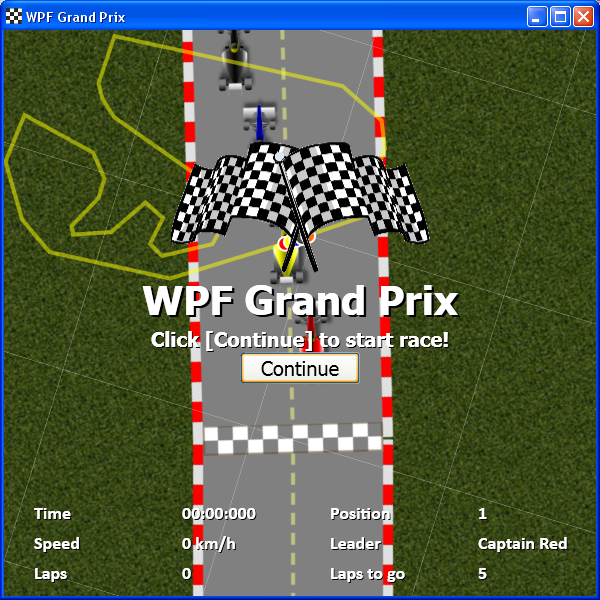
The stats panel is another kind of on screen display. It provides user with useful information about elapsed time, position, speed, race leader, laps and laps to go.
Figure 15. Stats panel: you know what's going on.
Here, we can see how the stats panel is updated in different moments, in different points of the code:
statsPanel.Laps = car.Laps;
statsPanel.LapsToGo = TOTAL_LAPS - car.Laps;
.
.
.
statsPanel.Time = new DateTime(diffTimeSpan.Ticks);
statsPanel.Speed = ((car.Speed / METERS_PER_TRACK_SEGMENT) /
	(gameLoopTimer.Interval.TotalMilliseconds / 1000.0)) * 3.6;
statsPanel.Laps = car.Laps;
statsPanel.LapsToGo = TOTAL_LAPS - car.Laps;
.
.
.
foreach (var pair in orderByVal)
{
	if (pos == 1)
		statsPanel.Leader = kartList[pair.Key].PilotName;

		if (pair.Key == 0)
		{
			statsPanel.Position = pos;
		}
		pos--;
}
The race is won when some racer finally completes all the 5 laps. When this happens, his name is displayed on the screen in a big, bold message, and in addition all cars are slowed down. This gives the realistic effect of racers naturally slowing down their cars that happens at the end of real races.
Figure 16. The first racer to cross the line after the last lap will be acclaimed as winner.
The application knows that a car has won the race when the car has just left the last track segment and entered the first track segment, and finally completed all the 5 laps:
if (car.NearestTrackLineSegment.Index != car.LastNearestTrackLineSegment.Index)
{
if (car.NearestTrackLineSegment.Index ==
car.LastNearestTrackLineSegment.Index + 1)
{
car.CircuitOffset += car.LastNearestTrackLineSegment.Length;
}
else if ((car.NearestTrackLineSegment.Index == 0) &&
(car.LastNearestTrackLineSegment.Index == trackLineList.Count - 1))
{
if (car.CircuitOffset > (circuitLength -
car.LastNearestTrackLineSegment.Length))
{
car.Laps++;
car.CircuitOffset = 0;
if (!gameOver &&
(TOTAL_LAPS == car.Laps))
{
gameOver = true;
var winner = GetWinner();
txtLargeMessage1.Text =
txtLargeMessage2.Text = string.Format("{0} Wins!",
winner.PilotName);
txtSmallMessage1.Text =
txtSmallMessage2.Text = "Click [Continue]
to start another race";
pnlMessage.Visibility = Visibility.Visible;
}
}
car.CircuitOffset += car.LastNearestTrackLineSegment.Length;
}
}
That's it! As said in the beginning of the article, WPF provides the tools. But it's up to us to take the most out of it.
I'd like to thank you very much for your time and your patience. Your feedback is really appreciated, so please leave a comment below, tell me what you liked and disliked in the application.
- 2010-11-30: Initial version
- 2010-12-05: Bezier curves added to the corners of the circuit. Enhancements on the A.I. driving logic. Enhancements on the camera movement logic.
- 2010-12-08: Article formatting, images added, comments added
- 2010-12-15: Explanation on A.I. (segment completion)


 General
  News
News  Suggestion
  Question
  Bug
Bug  Answer
  Joke
Joke  Praise
  Rant
Rant  Admin
Admin 


 .
.