
Introduction
Wow!! What a journey I was just on! This wasn't a pleasure cruise, but I enjoyed it quite a bit. I took plenty of pictures to share too!
A few weeks ago (a couple more days and I could put months here), I wrote an article called Guide to Win32 Memory DC.
One of the uses I wanted to display for a memory DC was its ability to be used with double-buffer painting. I had this picture in my mind of what I wanted it to look like.
Somewhere during development, it took a detour and it ended as a gradient-blended transition sweeping across the screen, alpha-blended with multiple images.
This article will describe the challenges and difficulties that I worked through to arrive at the visual effect I was aiming towards (however, I will not focus
on the effect in the previous article, more about this later). I found there are many samples for how to use both ::GradientFill and ::AlphaBlend.
Even if the examples on MSDN show all of the capabilities of ::GdiAlphaBlend, the results displayed on the screen do not provide any new insight on how the function works.
All of the effects could be recreated with calls to ::Rectangle and ::GradientFill. The samples are also performed on a white background.
I was confused by the results of my first attempts of alpha-blending when I moved away from the plain white background.
While looking for examples for the previous two functions, I discovered there is only one other documented function exported from this library, ::TransparentBlt.
Therefore, I decided to describe all three of these functions and cover the entire DLL for this article.
While thinking of possible demonstrations to apply these functions toward, I began to see how useful and flexible these functions are, even though they appear quite
rigid and simple. Ultimately, this article is about Image Composition. With the help of the functions in MsImg32.dll applied in some creative ways, dynamically
generated images that look great are only a few lines of code away, even written in C++ and using the Win32 API.
How to link MsImg32.dll with your program
MsImage32.dll is not the default link library list for Visual Studio. When you first use any of the functions described in this article without adding the library
msimg32.lib to your linker input settings, you will get linker errors similar to this:
1>------ Build started: Project: win32_msimg32, Configuration: Debug Win32 ------
1>Compiling...
1>MsImg32Usage.cpp
1>Linking...
1>MsImg32Usage.obj : error LNK2019: unresolved external
  symbol __imp__TransparentBlt@44 referenced in function @X...
1>MsImg32Usage.obj : error LNK2019: unresolved external
  symbol __imp__GradientFill@24 referenced in function @Y...
1>MsImg32Usage.obj : error LNK2019: unresolved external
  symbol __imp__AlphaBlend@44 referenced in function @Z...
1>win32_msimg32.exe : fatal error LNK1120: 3 unresolved externals
1>win32_msimg32 - 4 error(s), 1 warning(s)
========== Build: 0 succeeded, 1 failed, 0 up-to-date, 0 skipped ==========
The linker is complaining that it does not know where to map the function calls in the compiled code. The linker wants to know how to find the three functions described
in the error, and it could not find any definitions in the program for these functions. In this case, these are functions that will be loaded at runtime from
the Dynamic Link Library (DLL), MsImg32.dll.
There are two project based methods (that I am aware of) in Visual Studio to configure linker input libraries. The most common is the project settings, the other
is a #pragma statement for the linker. Both of these methods will add the name of the input link library to the list of command-line parameters when the linker is started.
Project linker settings
To access the link library input settings with Visual Studio 2008:
- Select the project which requires the link library definition
- Navigate with the menus to Project | Properties
- Select Configuration Properties | Linker | Input in the left-side tree-view
- Enter the name of the additional linker input library, in this case msimg32.lib
#pragma comment(lib, "lib_name")
When I am not writing portable cross-platform code, or the code module itself will be Win32 specific, I prefer to declare a #pragma comment(lib,"msimg32")
linker directive in the code module that will require the additional DLL. The .lib extension is implied on the name of the library, but you can add it if you prefer.
With this method, the settings will automatically be set for me if I move this code module to a different project. Project management can turn into a convoluted mess when
there are a large number of projects that all require custom configuration. This configuration method has virtually eliminated this problem for me.
#include <windows.h>
#pragma comment( lib, "Msimg32" ) // Linker directive for the topic dll
...
In my day, we only had 1's and 0's to program with...
When these functions were released in long forgotten Operating Systems (Windows 98 and Windows 2000), the process I described above was the approach that was required
to gain access to these functions. Since that time, these functions have also been added to GDI32.DLL and can be accessed like any other GDI call without requiring the extra
linker commands. However, these functions have been given different names to not conflict and break backwards compatibility. Each function has Gdi in the front
of the function name. If you reference these functions with the following names, there will be no need to specify the link library MsImg32.lib in your application.
Hey, at least you are now aware of other methods to link your other libraries to your code modules.
::GdiAlphaBlend(...)
::GdiGradientFill(...)
::GdiTransparentBlt(...)
Member introduction
There is surprisingly a lot to discuss when the next three functions are described. On the surface, they are simple. Their names describe exactly what they do.
However, if you start to think of ways these functions can interact and use them to create composite images, these functions can be combined to create awesome effects.
The best way I have determined to present all of the information I have gathered on these functions is to first introduce the exported members, with quick samples.
Then move into the more powerful techniques with compositing, as well as some of the non-intuitive problems that I ran into to and was able to work through.
::GdiTransparentBlt
::GdiTransparentBlt is the simplest of the three functions. This function provides the ability to use color-keying or Chroma Key type effect,
a.k.a. Blue-Screening (not to be confused with BSOD). A color is specified with the call that will become completely transparent when the source bitmap is drawn
on the destination bitmap. If you are familiar with ::BitBlt, you should have no trouble using ::GdiTransparentBlt.
BOOL GdiTransparentBlt(
__in HDC hdcDest, __in int xoriginDest, __in int yoriginDest, __in int wDest, __in int hDest, __in HDC hdcSrc, __in int xoriginSrc, __in int yoriginSrc, __in int wSrc, __in int hSrc, __in UINT crTransparent );
The documentation from MSDN states that all of the dimensions for this function are listed in logical units. The term relates to scaling modes
and viewport transformations that are supported in Win32 GDI. We're going to stick with the default mapping mode for this article, which is called MM_TEXT.
This mode maps one logical unit to one device pixel, where positive X is to the right and positive Y is down.
I previously compared this function to ::BitBlt, when it is actually much more like the function ::StretchBlt.
There are two extra size parameters provided for the source image. These values are the desired width and height to read from the bitmap, similar to the definitions
for the destination image. The difference here, is if the two dimensions do not match for the source and destination, the source image will be scaled to match
the specified destination dimensions. Overall, this is convenient and works well; however, your image quality can really suffer if you depend on GDI to scale all
of your images. I recommend you use the stretching capabilities of this function judiciously.
There is one other parameter in ::GdiTransparentBlt, and this parameter is different than the ROP codes that are found in ::BitBlt
and ::StretchBlt. The crTransparent parameter is a color which identifies the color to blot out for transparency.This is the Chroma-Key color in the bitmap.
A common convention is to make the first pixel of the image the transparent color. However, with ::GdiTransparentBlt, you have the ability to specify
any RGB tuple that you desire.
There is one final topic I would like to mention for this function, but I don't want to go into great detail. There are a few options available to allow you
to specify how the image is scaled when you are compressing an image into a smaller area. You can set this mode before your call to ::GdiTransparentBlt
with a call to ::SetStretchBltMode. These are the four modes and their basic behavior when merging pixels:
BLACKONWHITE: Uses the AND operator to determine which pixels are eliminated. This mode favors black over white pixels.COLORONCOLOR: Simply deletes the pixels for any lines that are removed.HALFTONE: Maps the pixels into blocks, and takes the average of the block to decide the color of the destination pixel.WHITEONBLACK: Uses the OR operator to determine which pixels are eliminated. This mode favors white over black pixels.
Look at this visual interpretation of what occurs during a call sequence to ::GdiTransparentBlt:
The sample code below will take two device context surfaces, and use ::GdiTransparentBlt to place the second image on top of the first with a transparency key
of RGB(0,0,0xFF).
HDC hImageDC = ::CreateCompatibleDC(hdc);
article::AutoBitmap bmpBob((HBITMAP)::LoadImage(NULL,
_T("codeproject_bob.bmp"),
IMAGE_BITMAP,
0, 0,
LR_LOADFROMFILE | LR_DEFAULTCOLOR));
::SelectObject(hImageDC, bobBmp);
BITMAP bm;
::GetObject(bmpBob, sizeof(bm), &bm);
::SetStretchBltMode(hImageDC, HALFTONE);
::GdiTransparentBlt(hdc,
0, 0, bm.bmWidth / 2, bm.bmHeight / 2,
hImageDC,
0, 0, bm.bmWidth, bm.bmHeight,
RGB(0, 0, 255));
::DeleteDC(hImageDC);
::GdiGradientFill
Gradients have become very popular over the last decade. They can be used to create very impressive effects with a minimal amount of work.
MSDN indicates that the fill for triangles is not required to be "pixel perfect", to simplify hardware acceleration. This implies to me that by using
this function, you will get some benefit in speed as opposed to implementing your own version of this algorithm. If you want more than the results
of my deductive reasoning, you can use the API ::GetDeviceCaps to query for the SHADEBLENDCAPS index. This will indicate
if the device is capable of blending rectangles (SB_GRAD_RECT) and triangles (SB_GRAD_TRI).
Up until writing this article, I really only used this function to create rectangular gradient fills. When I used it in that context, this function feels
like a whole lot of work. So I have generally avoided it unless it was exactly what I needed; however, it does not have to be that way, and hopefully after this
next section, you will find this API much simpler to use.
BOOL GdiGradientFill(
__in HDC hdc, __in PTRIVERTEX pVertex, __in ULONG dwNumVertex, __in PVOID pMesh, __in ULONG dwNumMesh, __in ULONG dwMode );
A cursory glance of the definition only reveals one parameter that we have used before, the device context. The last parameter is the mode for the type of gradient effect
to create. Surprisingly, there are only three modes provided, that does not seem like a whole lot of functionality. The first two modes are GRADIENT_FILL_RECT_H
and GRADIENT_FILL_RECT_V, for horizontal or vertical gradient fills, respectively. Two of the modes are used up for rectangle fills?! That's like getting
three wishes and wishing you knew what to wish for with the first two.
The third mode is GRADIENT_FILL_TRIANGLE. The gradient is spread across the three individual points of the triangle. Each vertex of the triangle can
be assigned its own color. This mode turns out to be the only mode that is required to do anything we could possibly want with gradients (I might be exaggerating,
but it wouldn't be by much). For real-time computer graphics applications, the models are divided into groups of triangles that are called meshes.
This process is called Tessellation. Any discrete polygon can be broken down to a set of triangles. Therefore we can build a mesh of triangles to create a gradient
fill for any shape, pattern, or direction. The first two modes can easily be implemented in terms of the GRADIENT_FILL_TRIANGLE mode by creating a mesh
of two triangles. So the developer of this API made good use of the third wish after all.
New data types
There are three new structs defined specifically for this function.
typedef struct _TRIVERTEX {
LONG x; Long y; BYTE Red; BYTE Green; BYTE Blue; BYTE Alpha; } TRIVERTEX, *PTRIVERTEX;
The TRIVERTEX will define points for the shapes that you wish to fill with a gradient. This structure allows the location and color definition of the vertex
to be associated with each other in this single structure. A small set of TRIVERTEX structures are required to create a successful gradient. There are two things
that stand out with this structure. We haven't run into the COLOR16 data type before, and one of the fields is called Alpha.
COLOR16
COLOR16 is simply a redefinition of the type USHORT, which is two-bytes large. This is significant, because all of the color channels up until
now have been defined by a single BYTE. Unfortunately, I am unaware of any features that take advantage of this increased value size. Another drawback is that
the single-byte color information that is normally provided needs to be placed in the high-order byte of the COLOR16 fields.
What a pain! It's as if they really didn't want developers to use this function.
I have declared a set of inline functions to help get me through this pain; I barely notice the extra work required any more. Each function will extract
the BYTE of data for the specified color channel, and shift it to the left by 8-bits.
inline COLOR16 ToColor16(BYTE byte)   { return byte << 8;}
inline COLOR16 RVal16(COLORREF color) { return ToColor16(GetRValue(color));}
inline COLOR16 GVal16(COLORREF color) { return ToColor16(GetGValue(color));}
inline COLOR16 BVal16(COLORREF color) { return ToColor16(GetBValue(color));}
The alpha channel
This is a very cool addition to the set of capabilities for the gradient fill. Unfortunately, the alpha channel is not applied to the DC surface
when ::GdiGradientFill is called. However, when a gradient is created, and alpha channel settings are specified, an alpha channel is generated.
Therefore a call to ::GdiAlphaBlend can use that channel information for more detailed blends. You will see in the application that I take advantage
of this quite often. It is a very simple process to create some nice blend effects.
Meshes
A mesh is a common term in computer graphics. A mesh is a set of triangles that are connected by their common edges. A mesh can represent both
2D and 3D surfaces. The final two structures defined for the ::GdiGradientFill function are similar in nature. Only one of the two will be used
for each call to the function, based on which dwMode is selected. These two structures reference the index of a vertex in the pVertex
array parameter, to define one polygon in the mesh. An array of these structures can be created and passed into the ::GdiGradientFill call to paint
a large set of polygons with a single call.
typedef struct _GRADIENT_RECT {
ULONG UpperLeft; ULONG LowerRight; } GRADIENT_RECT, *PGRADIENT_RECT;
typedef struct _GRADIENT_TRIANGLE {
ULONG Vertex1; ULONG Vertex2; ULONG Vertex3; } GRADIENT_TRIANGLE, *PGRADIENT_TRIANGLE;
Gradient samples
Here are a few images of the gradients that can be created with the function as it is presented in MSDN, along with the sample code demonstrated from MSDN:
Gradient for horizontal and vertical rectangle
MSDN: Drawing a Shaded Rectangle.
TRIVERTEX vertex[2] ;
vertex[0].x = 0;
vertex[0].y = 0;
vertex[0].Red = 0x0000;
vertex[0].Green = 0x8000;
vertex[0].Blue = 0x8000;
vertex[0].Alpha = 0x0000;
vertex[1].x = 300;
vertex[1].y = 80;
vertex[1].Red = 0x0000;
vertex[1].Green = 0xd000;
vertex[1].Blue = 0xd000;
vertex[1].Alpha = 0x0000;
GRADIENT_RECT gRect;
gRect.UpperLeft = 0;
gRect.LowerRight = 1;
::GdiGradientFill(hdc, vertex, 2, &gRect, 1, GRADIENT_FILL_RECT_H);
::GdiGradientFill(hdc, vertex, 2, &gRect, 1, GRADIENT_FILL_RECT_V);
I think it might actually take less coding to write a for loop to draw the same horizontal or vertical gradient, without the video acceleration of course.
Here are the results of the code from above:
Gradient with triangles
Again, this is the sample provided by MSDN for drawing a shaded triangle.
MSDN: Drawing a Shaded Triangle.
TRIVERTEX vertex[3];
vertex[0].x = 150;
vertex[0].y = 0;
vertex[0].Red = 0xff00;
vertex[0].Green = 0x8000;
vertex[0].Blue = 0x0000;
vertex[0].Alpha = 0x0000;
vertex[1].x = 0;
vertex[1].y = 150;
vertex[1].Red = 0x9000;
vertex[1].Green = 0x0000;
vertex[1].Blue = 0x9000;
vertex[1].Alpha = 0x0000;
vertex[2].x = 300;
vertex[2].y = 150;
vertex[2].Red = 0x9000;
vertex[2].Green = 0x0000;
vertex[2].Blue = 0x9000;
vertex[2].Alpha = 0x0000;
GRADIENT_TRIANGLE gTriangle;
gTriangle.Vertex1 = 0;
gTriangle.Vertex2 = 1;
gTriangle.Vertex3 = 2;
::GdiGradientFill(hdc, vertex, 3, &gTriangle, 1, GRADIENT_FILL_TRIANGLE);
Simplify the use of GdiGradientFill
While writing this article, I started to get tired of setting up all of the vertex definitions for the large number of gradients I created in the demo app.
Then I decided to write a small library of helper functions. The helper functions are defined in a pair of C++ files called BitBlender.h/cpp.
The inline functions I mentioned earlier for 16-bit color shifting are in the header file as well.
Here are two definitions to create a rectangular gradient. The first simply deals with RGB color tuples, the second will also allow you to specify an alpha channel value.
That's right! You can specify the alpha channel if you want. I added a few upgrades to calculate the intensity level of the pixel and assign that value to the alpha channel for that pixel.
It will cost you a little bit more in processing power, but now it's there if you need it.
namespace article
{
bool RectGradient(
HDC hDC, const RECT &rc, COLORREF c1, COLORREF c2, BOOL isVertical)
bool RectGradient(
HDC hDC,
const RECT &rc,
COLORREF c1,
COLORREF c2,
BOOL isVertical,
BYTE alpha1, BYTE alpha2 )
}
These function implementations are simply a more convenient wrapper around code very similar to the code presented from the MSDN sample.
Here is the new call that is required to create the horizontal gradient rectangle:
RECT rc = {0,0,300,80};
COLORREF black = RGB(0,0,0);
COLORREF blue = RGB(0,0,0xff);
artical::RectGradient(hdc, rc, black, blue, false);
::OffsetRect(&rc, 310, 0);
artical::RectGradient(hdc, rc, black, blue, true);
RadialGradient
Triangles are the simplest closed polygon that can be created. By arranging a mesh of triangles in different configurations, it is possible to create almost any type of gradient
effect imaginable. The first expanded use of the triangle gradient is an example I learned from Feng Yuan's book Windows Graphics Programming.
He demonstrates how to create a radial gradient emanating from a point.
For those that are familiar with Calculus, think about the approximations of integrals to calculate the area under a curve. Here is a pretty picture to refresh your memory:
Image source: Wikipedia
Calculating the area of a rectangle is a simple formula: width * height. If you continue to sub-divide the rectangles and fit them in the curve, then sum
the areas for all of the rectangles, you can get a closer approximation of how much area is underneath the curve. As the number of sub-divisions approaches infinity, the closer
your approximation will be to the actual value. For a more rigorous explanation and proof, consult your Calculus book.
Feng Yuan applied this principle to a circle, and sub-divided the circle into triangles (tesselation), rather than rectangles. The center point was a vertex each triangle had
in common, and this point was assigned the starting gradient color. The two remaining vertices for each triangle shared the second gradient color. The more triangle samples
that you include in the sub-division, the closer approximation you will have to a radial gradient. The number next to each shape on the image below indicates the number
of triangles that were used to render the radial gradient.
RadialGradient function
Here is the declaration of the function that I wrote to create the radial gradient shapes in the image above. Feng Yuan takes his implementation a step further
and allows the starting point to be offset from the center. I have kept this interface simple to reduce the number of parameters required to use the functions.
Also, I am not sure of what types of functionality exists in GDI+, and I want to avoid repeating too much of what may already be present in that library.
You can view the source for this function in the same file as the RectGradient function, BitBlender.cpp.
namespace article
{
bool RadialGradient(
HDC hdc, int x, int y, int r, COLORREF c1, COLORREF c2, size_t segments );
bool RadialGradient(
HDC hdc,
int x,
int y,
int r,
COLORREF c1,
COLORREF c2,
size_t segments,
BYTE alpha1, BYTE alpha2 );
}
AngularGradient
Up to this point in my exploration of gradients and bit-blending techniques, I had thought that I had grabbed all of the low-hanging fruit.
I was ready to move on to alpha-blending and call it good. Then it hit me, how incredibly simple it would be to create a gradient fill in a rectangle,
that was at any arbitrary angle, rather than just the horizontal and vertical cases.
For reference, this is what we are after:
AngularGradient function
Here is the function declaration for the function that I wrote, and directly below it is the call used to create the image above:
namespace article
{
bool AngularGradient(
HDC hdc, const RECT &rc, double angle, COLORREF c1, COLORREF c2, );
bool AngularGradient(
HDC hdc,
const RECT &rc,
double angle,
COLORREF c1,
COLORREF c2,
BYTE alpha1, BYTE alpha2 );
}
const COLORREF k_white = RGB(0xFF, 0xFF, 0xFF);
const COLORREF k_cpDarkGreen =
const double k_pi = 3.1415926535897932384626433832795;
double angle = (k_pi / 180.0) * theta;
RECT bounds = {0, 0, 300, 300};
COLORREF c1 = RGB(0x48, 0x8E, 0x00); COLORREF c2 = RGB(0xFF, 0xFF, 0xFF); article::AngularGradient(hBufferDC, bounds, angle, k_cpDarkGreen, k_white);
There are two features of ::GdiTransparentBlt that make solving this problem much simpler:
- The ability to assign a different color to each vertex.
- The ability to define a triangular mesh that describes a rectangle.
The four points of the input rectangle are known, two of the colors, and an angle for the gradient. That leaves two colors to determine. I was standing on my toilet hanging a clock,
and I fell and hit my head on the sink. That's when I came up with the idea for how to easily get the other two colors. Luckily, it only took 1 Watt to implement.
Imagine the target rectangle is inscribed in a larger rectangle that is aligned at the angle of the desired gradient. For those of you with poor imaginations,
here is another pretty picture.
Pretty good, but I meant with color:
Perfect!
The outer rectangle can be created with a few calculations to determine the four points of the rotated rectangle, and the original two colors.
Two triangles will need to be defined in the original rectangle to create mesh that is passed to ::GdiGradientFill. C1 is co-linear with the starting edge
of this rectangle, and C2 is co-linear along the ending edge of the rectangle. Therefore the colors for P1 and P2 will be C1 and C2, respectively.
We need to find the colors at P3 and P4:
Here are a few important observations from the previous diagram:
- A linear gradient can be mapped to a discrete line to create a Convex Combination from
C1 to C2. - The points
P3 and P4 bifurcate their respective edges.
The divided parts will be labeled A and B. - The length of
A can be calculated from the line segment P1P3 and the angle theta: A = cos(theta). - The length of
B can be calculated from the line segment P3P2 and the angle theta: B = sin(theta).
There are two things of importance that make calculating the colors at both of those intersections very simple:
- There are four similar right-triangles attached to the outside of the target rectangle by their hypotenuse. We can calculate the lengths of the edges to the intersect
from the triangles using basic trigonometry.
- This is a linear gradient stretched from
P1 to P2. The values calculated from step one can be converted to a pair of ratios.
Each of the two values can be determined by mapping its portion of the ratio onto the linear gradient.
Once the ratios have been calculated, the color for that point can be determined by multiplying the points ratio of the linear gradient, with the difference between
the start and end colors C1 and C2. This diagram depicts the information from the two previous points. The diagram on the left shows all of the calculations to determine the ratio.
The middle diagram shows the mapping of the four points to a linear gradient. The diagram on the right depicts how the color for each channel is calculated to create the final colors
C3 and C4 (Note: the alpha channel cannot be detected on the diagram because it is colorless and odorless).
Here is the actual code that is required to calculate the ratio of the sides and derive the intersection colors:
...
double s1 = (width/2) * cos(angle);
double s2 = (height/2) * sin(angle);
double len= fabs(s1) + fabs(s2);
double r1 = fabs(s1 / len);
double r2 = fabs(s2 / len);
int rDiff = 0;
int gDiff = 0;
int bDiff = 0;
article::GetColorDiff(c1, c2, rDiff, gDiff, bDiff);
COLORREF cA = RGB(GetRValue(c1) + (rDiff * r1),
GetGValue(c1) + (gDiff * r1),
GetBValue(c1) + (bDiff * r1));
COLORREF cB = RGB(GetRValue(c1) + (rDiff * r2),
GetGValue(c1) + (gDiff * r2),
GetBValue(c1) + (bDiff * r2));
...
There's always a corner-case
After I had this up and running, I was pleasantly surprised to see it actually work as designed the first time, with one exception. As I rotated the animation from 0 to 2pi,
the color gradients would pop back and forth. I tracked the issue down to the signs of the values that get calculated based on the quadrant the specified angle resides in.
Two minor tweaks were required to get the full 360° smooth gradient animation.
- The colors of the two interpolated points need to be swapped with each other every time the quadrant changes. This is due to the dragons that lie in wait at the bottom of the cos wave.
double quad     = (angle / (k_pi / 2));
int    offset   = int(ceil(quad) - 1);
if (0 == (offset % 2))
{
    std::swap(cA, cB); std::swap(alphaA, alphaB);
}
- Rotate the colors for each vertex to match the number of quadrants the original starting color has passed through. If
C1 passes through two quadrants,
rotate all of the colors by two places.
COLORREF clr[4] = { c1, c3, c2, c4 };
std::rotate(clr, clr + offset, clr + 4);
Sweet irony
The irony of this entire exercise for me, was to discover how much more complicated it is to calculate the rectangle that would encapsulate this rotated gradient,
then to calculate the gradient itself. I wanted to fit a square around the destination image, and rotate the bounding box as the angle changed. This was to prove to myself
that I had created the correct solution. At first, I was thinking I could get away with the use of the ratios as I had for the color calculation. However, the colors are interpolated
from a linear function, and the points are controlled by a cyclical parametric function with sin and cos.
Therefore, eventually I ended up writing the matrix rotation calculations required to rotate the different points of the original rectangle.
However, that would only rotate the polygon itself, then there was another calculation to determine the size of the smallest bounding box that could contain the original rectangle.
In the end, rotation calculations for both the width and height had to be performed, and the final points became sum of the components based upon the quadrant the point lies within.
Here is the code that rotates the bounding shape in the demo application.
LONG factor = (offset % 2)
? -1
: 1;
LONG halfWidth = GetWidth() / 2;
LONG halfHeight= GetHeight()/ 2;
double q1 = (halfWidth) * cos(angle*2) * factor;
double q2 = (halfWidth) * sin(angle*2) * factor;
double q3 = (halfHeight) * sin((angle-k_pi_2)*2) * factor;
double q4 = (halfHeight) * cos((angle-k_pi_2)*2) * factor;
pts[0].x = LONG(ctr.x - q1);
pts[0].y = LONG(ctr.y - halfHeight - q2);
pts[1].x = LONG(ctr.x - halfWidth + q3);
pts[1].y = LONG(ctr.y - q4);
pts[2].x = LONG(ctr.x + q1);
pts[2].y = LONG(ctr.y + halfHeight + q2);
pts[3].x = LONG(ctr.x + halfWidth - q3);
pts[3].y = LONG(ctr.y + q4);
std::rotate(pts, pts + offset, pts + 4);
Here is an image from the demonstration application that shows the rectangles gradient rotating, and the calculated ratios and other intermediate values that are used
to find the remaining two colors.
More complex gradients
There are a number of more complex gradients that can be created. Some that I have seen are conical, multi-color, linear with a point
of transition, and even gradients with transformations applied to them to create spirals, ripples, and other effects. Some of these I would like to explore further.
However, there are so many other things that I would like to dig deeper into with Windows GDI. I would also like to evaluate the capabilities of GDI+ before I try to re-invent the wheel.
Therefore, I must end the topic of gradients, and move on to the final function in msimg32.dll.
::GdiAlphaBlend
MSDN AlphaBlend sample app.
Alpha blending is a compositing process that creates the effect of a translucent or completely transparent image combined over a background image.
Alpha blending is extraordinarily useful. Effects can range from transparent holes that make the background visible through a foreground object,
to a translucent object that glows and shimmers.
The most basic form of compositing could be considered the ::GdiTransparentBlt API call described above. Alpha blending behaves very similarly to that API.
However, alpha blending is much more versatile, powerful, and can be quite a bit more complicated. It definitely takes a bit more code and patience to get a demonstration
with ::GdiAlphaBlend executing properly.
BOOL GdiAlphaBlend(
__in HDC __in int xoriginDest, __in int yoriginDest, __in int wDest, __in int hDest, __in HDC hdcSrc, __in int xoriginSrc, __in int yoriginSrc, __in int wSrc, __in int hSrc, __in BLENDFUNCTION ftn );
This function declaration looks almost exactly like ::GdiTransparentBlt, except the last parameter UINT crTransparent,
has been replaced with the parameter BLENDFUNCTION ftn. BLENDFUNCTION is a structure composed of four one-byte fields.
Therefore it will fit into a 32-bit buffer. Here is the declaration for BLENDFUNCTION:
typedef struct _BLENDFUNCTION {
BYTE BlendOp; BYTE BlendFlags; BYTE SourceConstantAlpha; BYTE AlphaFormat; }BLENDFUNCTION, *PBLENDFUNCTION, *LPBLENDFUNCTION;
Each of these fields require more of a description than what will fit in a one line comment blurb, but not much.
BlendOp: There is only one blend operation defined at this point, AC_SRC_OVER. When the two images are blended, the source image will
be placed on top of the destination image before the blend. The alpha value of each source pixel will determine how much of the destination image becomes visible.BlendFlags: This value will help delay the inevitable ::GdiAlphaBlendEx. For now, it must sit quietly and be set to 0.SourceConstantAlpha: This is a global transparency constant that will be applied to every pixel during the blend operation. The values range from
0 to 255; where 0 is 100% transparent and increases to 255 which is 0% transparent, completely opaque. This value will combine with any source alpha as well.Example: If you have a source pixel alpha at 50%, and a source constant alpha at 50%, the result will take 50% from the source pixel during pre-blend, and another
50% with the constant blend, leaving 25% source and 75% destination.
AlphaFormat: Indicates the type of alpha channel information encoded in the image. If this value is set to 0, the images will be blended
only using the SourceConstantAlpha parameter.The value AC_SRC_ALPHA indicates the image is encoded with per-pixel-blending. This extra information will be used when blending the images,
but there's a catch, read the fine print from MSDN:
| Value | Meaning |
|---|
AC_SRC_ALPHA | This flag is set when the bitmap has an alpha channel (that is, per-pixel alpha). Note that the APIs use pre-multiplied alpha,
which means that the red, green, and blue channel values in the bitmap must be pre-multiplied with the alpha channel value. For example, if the alpha channel
value is x, the red, green, and blue channels must be multiplied by x and divided by 0xff prior to the call. |
The function will not perform the per-pixel blending itself. You, the caller of the function, must ensure that image is pre-blended,
before you call ::GdiAlphaBlend with the AC_SRC_ALPHA value set.
What effect does pre-blending the alpha channel have on the image?
The 24-bit RGB color scheme is capable of displaying 256 shades of each of the colors Red, Green, and Blue; the largest and brightest value per color
channel is 255 or 0xFF in hexadecimal. Alpha-blending combines a portion of two pixels to create one new pixel. The sum of the values for the channels
of two pixels cannot exceed the maximum value of 255. The alpha multiplication scales the source pixel to be within a desired threshold where the maximum
value for the channel will be the same value of the alpha channel.
Therefore, the pre-blend step will reduce the brightness of the source image, and leave the difference of the value for the destination the channel color.
When the pre-blended source image is passed into ::GdiAlphaBlend, the API will scale the values of the destination pixel, then add the value of the source pixel
to create the final color.
The images below show how the bitmaps are affected by the pre-blend step:
| | |
Source image
| Alpha channel
| Pre-blended source image
|
| | |
Destination image
| Final image without pre-blend
| Final image with pre-blend
|
A few weeks ago, when I was trying to eek out the blended effect I was going for with this article Guide to Win32 Memory DC,
I was quite a bit frustrated by the meaning for AC_SRC_ALPHA. The values in my images were becoming saturated, that is the sum of the two pixels
exceeded the maximum value of 0xFF for that channel. This caused weird artifacts to appear on the image, such as large bleach spots, or added bands of an unexpected color.
I had noticed the sentence on MSDN that indicates the image should be pre-blended, but I continued to ignore it because I was getting the results I wanted up until I ran into problems.
Sometimes your images will work without pre-blending
I didn't uncover all of the mysteries of the ::GdiAlphaBlend function when I completed my article on Win32 Memory DCs. When I first created my screen wiper,
it was on a blank white canvas. I wanted the color of the wiper to fade into the canvas. With a blank canvas, I easily achieved this by blending from the color of the wiper
to white. Then I added some rectangles in the background to make the flickering more prominent. This is what I had created:
One of the many abominations possible to create with ::GdiAlphaBlend.
I fumbled around for a bit, troubleshooting, and trying to figure out what was happening. Yes, the issue was I didn't pre-blend the image alpha.
However, before I learned the actual reason for my mistake, I stumbled upon a solution that worked in this scenario. I created my wiper to fade into black rather than white.
The color black adds 0 intensity for each color channel of the source image. The chances are far less that a saturation point will be reached if your gradient does not use brighter colors.
So that program has the potential to create the saturated alpha-blend, however it currently does not use the colors that would create that condition.
This is what the raw image of the wiper looks like if it is painted to the screen with ::BitBlt rather than ::GdiAlphaBlend:
The wiper painted with BitBlt.
If you have not yet visited my Memory DC article, this is what the final result looks like:
Let's dissect a reference blend image
This image is an example of alpha-blending a gradient rectangle that transitions from green to red. The gradient is blended onto five different colored bars to demonstrate
the effects that occur with blending. No pre-blending was performed on the source image. Therefore, only the addition of the pixels was performed, and this created
a variety of artifacts in the image below.
I have annotated points of interest in the image. Items 1-6 were painted onto a white background. More details describe the other points of interest:
- Green to red gradient bar simply painted on the screen.
- Red reference bar.
- Black reference bar.
- Green reference bar.
- White reference bar.
- Blue reference bar.
- Green to red gradient bars similar to item one. However, these two bars were added to the image with
::GdiAlphaBlend.
- Green + red build up towards orange. However, the red becomes saturated and rolls over into the green channel.
- Green continues to decrease and transitions back to red.
- Green and red fade as they both move towards the center. However, they are being added to a white background which is already its maximum value.
The maximum values of green + red create yellow, then saturation occurs.
- The values roll over into the blue channel. As the transition continues towards the right, the green channel becomes saturated, and finally
the blue channel is saturated as well. The result is white.
- Pure awesomeness!!! After fumbling around in confusion while writing my previous article, I found that if I blended my images on a gradient that faded
into black, everything worked perfectly. It was counter-intuitive at first. However, once I realized I was not pre-blending any alpha values, and the color black is 0,
I realized you cannot saturate the image with the blend of this combination.
- As green fades into red, no channels are saturated, and the maximum green + red is reached at the right to create yellow.
- Similar to a.
- Green fades to a small set of blue shades. However, red starts at its maximum value, and for RGB, red + blue creates magenta.
Note: This is not a test for color-blindness. However, if you only see two colors in the box above, you may want to get tested.
When you do end up having to pre-multiply the alpha channel into your image, the calculation is straightforward. The most difficult part is getting access
to the pixel data to perform the calculation on every pixel in the image. There are two functions that give access to read and write to pixels,
::GetPixel and ::SetPixel. However, they are not good enough, just like that boy that's dating your daughter. I don't know why that boy is not
good enough, however, I can tell you what is wrong with these functions. The functions only give access to the RGB components of the pixel. Even if ::GetPixel
and ::SetPixel could give access to the alpha channel, they are very slow, also like that boy.
Direct access to the bitmap memory buffer is required. This can be achieved with a Device-Independent Bitmap (DIB). The calculations with this method is orders of magnitude faster,
however, it also requires covering a different topic which requires a lot of attention to do it justice, BITMAPs and DIBs. That's why I decided to gloss over that topic.
Maybe I will write an article on bitmaps next. When you do have raw access to the 32-bit color bitmap, here is the code that will pre-blend the alpha channel into the image for you:
for (y = 0; y < ulBitmapHeight; y++)
{
for (x = 0; x < ulBitmapWidth; x++)
{
UINT32 &rPixel = (UINT32*)pvBits[x + y * ulBitmapWidth];
UCHAR ubAlpha = rPixel >> 24;
float fAlphaFactor = (float)ubAlpha / (float)0xff;
rPixel = (ubAlpha << 24) | ((UCHAR)(GetRValue(rPixel) * fAlphaFactor) << 16) | ((UCHAR)(GetGValue(rPixel) * fAlphaFactor) << 8) | ((UCHAR)(GetBValue(rPixel) * fAlphaFactor)); }
}
I have created a function that is simple to call and will convert a 32-bit bitmap into a DIB, and perform the alpha multiplication step, and place the result image back
into the original bitmap.
bool PreMultiplyBitmapAlpha(
HDC hdc, HBITMAP hBmp );
Hopefully you're still with me, because all of the boring stuff is out of the way, and there will be nothing but good stuff from here on out.
The jaggies
For those not familiar with this term, it's computer slang for "crappy graphics". Actually, it is the aliasing artifacts that appear on raster (bitmap) displays because
of a low resolution to detail ratio for the display. This is often overcome by anti-aliasing techniques. Alpha-blending is one of the anti-aliasing techniques.
Alpha-blending is used to blur the edges if the low resolution edges, and simulate the appearance of a fractionally filled pixel. Sub-pixel sampling is another name for this approach.
Let's look at an example up close. Three images are displayed below:
- Bob with the "jaggies".
- Bob alpha-blended with the background.
- Bob in bitmap editor with alpha-channel visible. Notice the sub-pixel blending highlighted in orange.
For the most part, image 2 is a large improvement over image 1. However, compare Bob's left foot in image 1 and image 2.
The edge of Bob's foot in image 2 has now become blurry. The sharp crisp edge has been traded for a softer smooth edge with a slight loss of detail.
This is a trade-off that exists between discrete raster images, and trying to approximate colors with sub-pixel rendering.
Image 2 had to be exported from my image editor to put it in a format that I could easily load into my sample programs. During the export, I had to render the image with
a background color. The background color was set to white. Therefore, all of the alpha values from the working image displayed in image 3 were blended with a white background.
Image 2 will look fantastic, as long as I always paint it on a canvas with a white background. If image 2 is painted on a different colored background, this is the result:
- Bob rendered on a white background.
- The white background is flood-filled with blue to change the color of the background.
- Bob rendered on a blue background from the start creates a cleaner image.
The white outline in image 2 is an artifact of the alpha-blended channel combined with a white background. The alpha channel information is lost when the image is rendered
on any color of background. The smoothing performed to reduce the effect of the jaggies has blended varying shades of black, the outline color of the object,
with the background color. We're ready to answer the questions.
Why would I need an image with alpha channel values for every pixel?
To keep the ability to programmatically composite your image on top of any possible background, including dynamic backgrounds that change with time.
Why doesn't Microsoft just multiply the alpha channel in ::GdiAlphaBlend?
Performance
Unless your source image is constantly changing, the pre-multiplication step only needs to occur once. If ::GdiAlphaBlend is used in a context where it will
be repeatedly called on a static source image, this could be extremely taxing on the systems resources and create an enormous reduction in performance. Look at the statistics
for the scenario below to help put this point into perspective:
- A 24-bit color, 200x300 pixel image contains 60,000 pixels
- 3 channels of color
- Animate at 30 frames per second
- Requires 60,000 * 3 * 30 pre-multiplications ~(1 mul, 1 div per calculation)
- Totals 5.4 million redundant calculations per second
If you are concerned about performance and ::GdiAlphaBlend, query your display device for its SHADEBLENDCAPS capabilities.
You can query for this information with ::GetDeviceCaps. If the device has this capability, the blending operations will be accelerated by your adapter.
Sorry, I don't have any numbers to indicate how well this function performs accelerated. I can say, I have never run into any limiting paint issues from using this API.
If I were to write another game, I wouldn't use GDI or GDI+, I would use DirectX.
Demonstration
This app started out as a blank canvas on which I experimented with different ways to compose images from the three functions described in this article.
The first concept I explored was the obvious one, glossy orbs. I looked through a few Photoshop tutorials on the web, and created one programmatically. Here is an example:
How did you get stuck in that orb Bob?
"Image Composition"
The application has three different areas of functionality that demonstrate code that I developed while experimenting with the APIs and developing tools to make use of them simpler.
Every button, control, or whatever is painted by code I wrote. I was playing around trying to create a nice looking rectangular button. I stopped when I reached something that I liked.
I used these for two days, then I realized that I had re-invented the silver themed buttons from Windows XP. Oh well, if this were an article about buttons, I would
have created something else, but it's not, so it's what I am going with.
I kept playing around with the functions, trying to recreate an effect like the radial gradient. Just about when I was ready to move on, I would come up with another
way I could apply these functions to create a gradient effect. The same thing happened when I moved on to alpha blend. The program still looks a bit busy and complicated.
When I realized I was programming while holding a bedazzler, I decided it was time to stop adding bling and try to wrap it up.
In summary, the demonstration application shows many ways to create visual effects with a small handful of raw GDI functions. Some of the things are probably much simpler
with GDI+ or the equivalent .NET Graphics object. However, now you can see how powerful the raw primitive functions in GDI can be, and image composition is at your fingertips.
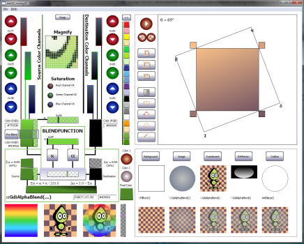
| Angular gradient demo
This demonstration is on the top right-hand corner of the program. It is the code I was working with to prove to myself that I had in fact created the correct solution
to calculate and draw a gradient at any angle. Press the Play button and the angle will start counting in whichever direction you choose, and animate the gradient rotating
to match the current angle. There are silver buttons to turn on and off the various features, such as polygon outlines, outer-gradient, and trace the outline that the bounding
box creates. You can also change between the square and horizontal or vertical rectangles.
|
| Image composition demo
This is the window in the lower right-hand corner of the application. This portion demonstrates step-by-step the image composition process required to create the final orb.
There are a few controls to interact with to change the appearance of the orb, such as whether the orb will appear translucent or not, if a reflection is used, if an image
is transparently blitted. For each step, the image to be added to the composition and the name of the function used to combine the image are listed.
|
| Bit blender demo
I had a lot of fun creating the bit-blender demo, that's why I saved it for last. I have plenty to say about it. I actually feel a little bit ashamed leaving the Orb Composition
demo in this app next to the bit blender. In the beginning, the quality of the Orb is all that I intended to attain, and in the end, that demo didn't get near the amount
of attention the Bit Blender received.
Disclaimer: Use at your own risk. I make no guarantees that you will create a stellar color combination and cannot be held liable for any god-awful
color combinations that you create.
|
Learning through experimentation
The documentation for the BLENDFUNCTION structure has a table of calculations that indicate how the source and destination images will be blended based
on the configured parameters. Unless you spend some time playing around with blending the colors, the table probably won't help you determine which configuration you are after.
While the AlphaBlend sample program from MSDN does show the output of all of the configurations, what is happening is not immediately apparent. There are many reasons this
sample usage falls short.
The most obvious reason is the same output can be created with far less code, using simpler APIs, so why go to the trouble they are demonstrating?
I described the blend issues that I ran into with blending to a plain white background vs. a multi-colored background. I wanted to create a visualization
of the BLENDFUNCTION calculation table, and make it a bit easier to see what is happening with ::GdiAlphaBlend. The image we dissected above was
my first attempt to visualize the possibilities. I quickly abandoned that path as it was too complicated, and didn't even begin to demonstrate what happens.
I then moved to a color channel selection scheme for the source and destination colors of a single pixel. The layout changed quite a bit through the development.
Then I started to represent the metaphor of a blending machine with the actual BlendFunction structure and call to ::GdiAlphaBlend. The program will now allow
you to experiment with the blending of individual channel colors and alpha levels to see the resulting color.
BLENDFUNCTION
BLENDFUNCTION appears to be a simple piece of code machinery. However, you'll want to watch your fingers when you are using this tool. It can get quite complicated,
and be un-intuitive at times. You will find yourself returning back to the owner's manual quite often.
There are three color channels for both the source and destination that are combined to create the color for a single pixel. The left side is the source, and I designate
any references with Σ (Sigma). The right side is the destination pixel that will contribute to the blend, and I reference
it with Δ (Delta). The two long tall boxes represent the input pixel for a particular run of ::GdiAlphaBlend.
The RGB code is indicated in the edit box near the top edge. If you create a cool color you like, you can copy the text out of the boxes, but I did not make them capable
of accepting input (maybe if enough requests come in I will add that in the BitBlender 2012 Pro Edition).
α is for alpha
Now the left-side looks a lot busier than the right-side. If you think it is gauche, you are correct, but only if you are from France. There is an added pixel component
for the source, that is the alpha channel. The horizontal rectangle designated by α is the alpha channel input.
The input value represents 8-bits (0-255). At this time, you can click to update the position and value of the alpha input; I didn't add keyboard support or click
and drag like a scrollbar (this is also slated for the Pro Edition). When the bar is selected all of the way to the left (0xFF), the α channel box
will have a solid fill as the same color as the source pixel. As the bar is moved to the right, the value will decrease. Transparency is represented by fading from the color
of the specified channel, to a white and gray checkerboard pattern.
Pre-blend button
I wanted to make a visual representation for each calculation in the process. My favorite step is the the Pre-Blend button. The button is enabled to pre-blend
the alpha channel and adjust the color. You can press the button and turn off the effect. The effect is just another gradient. I must have drawn hundreds of those by now.
The button is what is cool. I ended up creating a glass pane that hovers over the color field with translucency and a simulated refraction effect.
When the pre-blend is active, the color at the bottom of the pane will be adjusted by the appropriate amount specified by α.
Κ is for SourceConstAlpha
There are two input parameters that are meaningful to the BLENDFUNCTION. Remember?! SourceConstAlpha (Κ)
is the easier of the two values to control and operate. Κ will equally attenuate every pixel in the source image,
unlike α which has a specific value defined for each pixel. Κ is a good value to manipulate
if you would like to create a fade-in or fade-out animation, or to simply create a uniform blend over a region on the display.
If both Κ and α are used, Κ will further attenuate
α by a proportional value before the alpha-blend occurs.
In the BitBlender, you can enable and disable each of the alpha-blend components, pre-blend, per-pixel blending, and SourceConstantAlpha.
You have already been introduced to the Pre-Blend button. Here are the buttons for the remaining two functions:
| SourceConstantAlpha Κ is always processed. If Κ = 0x00, the source will be completely
transparent, and only the destination image will be used. If Κ = 0xFF, the source image will be completely opaque, and only the source
image α will be considered in the blend.
|
| Per-pixel blending is performed when AlphaFormat = AC_SRC_ALPHA. This is basically an on or off feature. The other option is 0, which will cause
the alpha channel to be completely ignored and only use the value from Κ for blending.
|
Example:
α is configured to use 50% source pixel and 50% destination pixel. The same configuration value will be set for Κ
as well. The values are normalized to be between 0 and 1.0 to prevent any values from saturating the color channel. This is done by dividing the value by the maximum of 255
for an 8-bit channel. For the example, values between 0 and 1.0 will be used.
α = 0.5
Κ = 0.5
The pre-blend step will first attenuate the color channels by the proper α. Let's perform the calculation to determine the total
contribution to the final pixel from the source pixel. For the moment, our only concern is how to split up the share for each pixel input. There is a total of 1.0
to divide between the two sources.
Σin = 1 * α = 1.0 * 0.5
Σin = 0.5
Κ will now be processed. This value will be multiplied with the source pixel that enters the BLENDFUNCTION,
which is the value Σin. Σα will represent the final source contribution to the pixel blend.
Σα = Σin * Κ = 0.5 * 0.5
Σα = 0.25 = 25% => 0x40
One more step before the final blend. The contribution from the destination pixel needs to be calculated. The destination pixel will receive the remainder of the percentage
not taken by the source pixel. The destination contribution will be represented by Δα.
Δα = 1 - Σα = 1 - 0.25
Δα = 0.75 = 75% => 0xC0
The image below shows the visual representation of this example calculation:
Up to this point, all of the components have been explained and should be able to be matched up with the example equation given above, with the exception of the silver box in the middle.
This value is not configurable. Think of it as a scale. It moves from left to right and will be positioned according to the amount each pixel source contributes to the final value.
From the example above, 25% of the input will be from the source pixel. Therefore the indicator scale displays a 25% portion for the source, and 75% portion for the destination.
Each of the resulting alpha values and pixel colors are displayed in the set of boxes at the bottom. Same order as before, Source on the left, Destination on the right.
Measure once, and cut twice...
At least that's how it always seems to go for me with computer graphics when I'm trying to get the right look. The only step left is to blend the source
Σα and destination Δα values together. The result will be the color for a single pixel in the final image. This image depicts blending:
The calculations that were used in the example above are listed below the silver portion box. The formulas will change based on the input configuration combinations
for α and Κ. Here is a table that breaks down the equations that will be displayed based on the different
combination of inputs. There are two values that can be on or off, therefore there are four possible calculations.
| Κ | α | Equation Δα | Equation Σα | Image | Description |
|---|
| 255 | 0 | 0.0 | 1.0 | | Κ is set to the maximum value and per-pixel α is disabled.
Therefore only the source image will be used for the entire bitmap. |
| 255 | AC_SRC_ALPHA | 1.0 - Σα | α / 255.0 | | Κ is set to the maximum value, and per-pixel α is enabled.
Therefore α is normalized then used to attenuate the source image Σα. Δα receives the portion that remains. |
| < 255 | 0 | 1.0 - Σα | Κ / 255.0 | | Κ is partially transparent, and per-pixel α is disabled.
Therefore Κ is normalized then used to attenuate the source image Σα.
Δα receives the portion that remains. If the image has an alpha channel, its values are ignored. |
| < 255 | AC_SRC_ALPHA | 1.0 - Σα | Κ * α / 255.0 | | Κ is partially transparent, and per-pixel α is enabled.
Therefore α and Κ are normalized then used to attenuate the source
image Σα. Δα receives the portion that remains. |
A few extras
| Pixel inspector
If you want to inspect what is happening with the calculations as you change the settings for the blend images, move the cursor over the image.
The source, destination, and alpha channel values will be read for the pixel, and automatically configured into the Bit Blender. As you scroll across the images,
the settings will dynamically change for each new pixel. If you would like to inspect a specific pixel, click the left mouse button, and updates will be disabled
until you scroll off of the image and back onto any of the three images at the bottom of the Bit Blender.
|
| Saturated channels
I added some indicators to report if the current color and alpha settings would create a saturated pixel. I don't believe that what I calculate in this condition
will match what your video card returns. However, this is a convenient indicator for when you are playing with the settings and not pre-blending the alpha channel.
|
| Quick colors
While playing around, I got tired of re-entering colors by hand. So I added a small selection of colors to quickly set the pixel color for the source or destination channel.
The chevron points to the left to indicate the Source Pixel that will be configured, and to the right for the Destination Pixel. A vertical bar will also run on the side
of the buttons either on left or right, as another indicator of which pixel will be configured when you select a quick color.
|
| Zoom
The zoom window will magnify where the cursor is over when it is moved over the blending images at the bottom. The magnification is at x4.
I added this so I could inspect close up details, without having to start magnify. That program really annoys me to leave it running while I start and stop a program
that I am debugging. The zoom view will follow the cursor until the left button is clicked. The magnified view will be frozen at that point until the cursor is moved off that image,
and onto any of the blend images.
|
About the code
The program is written using standard C++ access to Win32 API calls, therefore MFC and WTL are not required to build and run the samples. I have included the project as
a VS2008 project. I have separated most of the code that was written for demonstration into a separate file called MsImgUsage.cpp. There are also two utility files
that I created to make the code cleaner and factor out the tedious and error-prone aspects of GDI programming. You may find these files useful.
I have encapsulated all of the demonstration code in the article:: namespace to help developers unfamiliar with Win32 GDI be able to distinguish the functions
that I wrote from the API calls. I have tried to reference all of the Win32 API calls with the global namespace operator, such as ::CreateCompatibleDC(...).
Hopefully I did not miss any.
I think it needs some more Paulish
All of the demos were in place, all of the behavior that I was going to implement was complete. I was taking screenshots to update the article, and this is what I am looking at:
Everything else looked so nice and smooth. For most color combinations, the dynamic button colors work well. And then there are these jaggies just mucking up the display.
I kept thinking, "I should do something about it, nah, that's out of scope. I'll write an article about it and improve it later."
Then I remembered a partially completed anti-aliasing circle implementation that I made back in 2004, at least according to the comments. The circle part works great,
but something shiny jingled near by and I became distracted before I could complete the rest of the function. So it is not perfect, but it is good enough for what I needed.
I put it in, and after a little bit of nudging, this is what I ended up with:
I couldn't believe the improvement. I knew it would look better, I just didn't think it would help that much. The anti-aliased circle algorithm is based
on Xiaolin Wu's anti-aliasing circle algorithm. I hope to revisit this function and complete it in the future. You can find the current implementation in the file aa_ellipse.cpp.
One last thing that seems useful to point out, is these controls and gradients look pretty good at the size that I have them displayed at for buttons, ~50 pixels.
However, in the enlarged version, you can see the blending artifacts, the faint lines where the colors almost blend, but not quite. These orbs were rendered with
32 segments in the radial gradient. Increasing the number of segments would help resolve this artifact if it becomes an issue for any item you are trying to display.
Useful code
The sections of code that I believe you will find useful in the demonstration are marked like this //!!!. There is also a short comment that describes
what you should be able to take from the code snippet. (Expect to see plenty of //!!!, this is riveting stuff!)
int ctx = ::SaveDC(hDC);
::SelectObject(hBufferDC, g_hPenBlack);
::SelectObject(hBufferDC, ::GetStockObject(WHITE_BRUSH));
DrawShapes(hBufferDC, hRightRgn, width, height, g_group1, g_isGroup1Active);
DrawShapes(hBufferDC, hLeftRgn, width, height, g_group2, !g_isGroup1Active);
::RestoreDC(hDC, ctx);
This time, there are quite a few chunks of code you may find useful from this demonstration application. Earlier in the article, I introduced the BitBlender.h file.
This file creates a few utility wrappers around functions from msimg32.dll to make using them require much less code and even add new capabilities.
There are a few other utility files and objects that you may find useful.
AutoGdi.h
While I have omitted the MFC and WTL dependencies, I have not eschewed C++ style and conventions altogether. AutoGdi.h contains a set of utility classes
to help manage GDI resources. These objects factor out common boilerplate code from the code where your real work is performed. This will hopefully allow you
to write more correct code, rather than getting lost in the minutia. These objects provide a no frills implementation and may not provide the most convenient usage for all situations.
However, they have done a great job of cleaning up after me whenever I get a whim to create a brush with a new color.
article::Auto<HGDIOBJ> and article::AutoSaveDC
The first class I implemented in this utility header is a template that provides a set of GDI cleanup objects intended to be created on the stack. When the object goes out
of scope, the GDI handle will automatically be deleted. Another class defined in this file is AutoSaveDC. This class will create a save point with the device context,
and automatically restore your DC to the state it was in, immediately before the AutoSaveDC object was created. Here is an example of how these objects are used.
The copy constructor and assignment operators have been disabled for these objects. This greatly simplifies the internal management that is required to maintain the object.
The object has an explicit constructor declared for the type of HGDIOBJ which it is to maintain, and it also has a type converter function
to convert the object back to the type of handle it represents.
{
article::AutoPen greenPen(::CreatePen(PS_SOLID, 1, RGB(0,255,0)));
article::AutoBrush orangeBrush(::CreateSolidBrush(RGB(200,200,0)));
if (...)
{
article::AutoSaveDC save(hdc);
::SelectObject(hdc, greenPen);
}
}
I am going to explicitly state this, so there is absolutely no confusion. These objects are only intended to be created as auto objects on the stack,
inside of a function or class. They will not do anything for you if you dynamically allocate them with new and forget to delete them, or add the static
qualifier to its definition.
article::MemDCBuffer
I found myself copying the setup and teardown code for creating a double-buffer with a memory DC quite a bit. So I created the MemDCBuffer class as well.
This is another light-weight class to be declared on the stack, or in some context that will allow it to be properly released. The class will create and manage a memory DC
and a compatible bitmap to a specified DC. The object can then be used for any call you would normally use a handle to a DC. When you would like to copy the contents back
to the original DC, call MemDCBuffer::Flush(HDC) with the handle to the destination DC; in most cases, it makes sense to use the same DC that was used
to create the MemDCBuffer.
case WM_PAINT:
{
PAINTSTRUCT ps;
HDC hdc = ::BeginPaint(hWnd, &ps);
article::MemDCBuffer dblBuf(hdc);
::Rectangle(dblBuf, 10, 10, 250, 250);
dblBuf.Flush(hdc);
::EndPaint(hWnd, &ps);
}
break;
Conclusion
It took me much longer than anticipated to create this article the way I thought it should be done (a little over 6 weeks) to describe three functions. This is the last time I write
an article about an entire DLL. It only gets worse from here with Windows. GDI32.DLL exports 690 symbols, I think I will just take them on a few at a time from now on.
With respect to Image Composition, your imagination is your only limit. Every time I thought I had reached a plateau for what would be simple enough to demonstrate, and informative,
I would come up with another idea that could create something not available in the raw APIs, and look great. I plan on continuing to develop the library of helper functions that
I started here. I will update this article, or write a second installment when I do improve them. By far I have gotten the most use from ::GdiGradientFill,
however, as I have become much more familiar with ::GdiAlphaBlend, I am starting to see new and unique ways this function can be applied as well.
All of the vector based languages and frameworks that are popular these days for GUIs depend on the technologies and concepts demonstrated in this article.
With a few well designed objects, the quality of scaled vector interfaces can be available to your natively developed applications through image composition.
The raw components are all there. In fact, GdiPlus is a library that builds upon the Win32 GDI just as I have started to in this article. So go out, and make something pretty.
History
- September 08, 2011: Original release.


 General
  News
News  Suggestion
  Question
  Bug
Bug  Answer
  Joke
Joke  Praise
  Rant
Rant  Admin
Admin 


