Introduction
I was looking for some application to do with controller, it looks like that one of the dream jobs is the robot.
So I decide to write a small article about robots. "robots for all".
Work with robots, is interesting, but is not easy. To make an exhaustive explanation, I should write a book. I try to explain the logic, but I must give you a lot of link to study in deepen the arguments.There is a lot of calculation to do. But we can utilize a program of Computer Algebra System. I utilize Maxima: http://maxima.sourceforge.net/. So we can concentrate our effort on the program, and make easily each kind of try. When you will copy from maxima, it is already C/C++ formatted. So if you give the right name of the variables, copy paste becomes very easy.
Robot type
Exists two big family of robots. Parallel also called close cinematic http://en.wikipedia.org/wiki/Parallel_manipulator, the have small room of operation but can reach very high speed and force.
Open cinematic or serial http://en.wikipedia.org/wiki/Robotic_arm#Types, such the cartesian, the scara, or our articled arm.
The parallel is heavier to treat, because we can not generalize, and must studied time for time. Meanwhile with the open cinematic, we can track a general road.
This is our champion:

Problem Type
The problem in the robot kinematic are two:
- Direct kinematic
- Inverse kinematic
The direct problem is retrieve the position of the end-effector (the last arm, with your tool to keep, weld, paint etc.), given the constraint of the motors.
The inverse problem is retrieve the constraints of the motors know the position and orientation in the space. This is, I presume, the normal situation when we work. "The piece is there, we must bring the robot there" But is also hard to solve. And not ever is it possible, analytically. There is some particular configuration that allow us to solve it, ideal for small micro-controller, with small calculation power. Our configuration is an "anthropomorphic arm" that allow us to solve analytically.
Direct Problem
For the direct problem, we can just utilize matrix. It looks hard, but after understood the logic it is not impossible. It is just an algorithm to learn.
First you must know what are the rotation matrix. These are the basic rotation matrix, http://en.wikipedia.org/wiki/Rotation_matrix#Basic_rotations. Our system matrix is obtained with opportune multiplication of these matrix.
We need to define an common notation. The notation normally in use, is the Denavit-Hartenberg-notation. http://en.wikipedia.org/wiki/Denavit%E2%80%93Hartenberg_parameters
These notation defines the Denavit-Hartenberg parameters. (these are simplistic definitions, refer to the link for deepen ones) :
- the z-axis is direct along the axis of the joint. Important the z-axis is the axis of rotation of the motor. Translations in z-axis are called
dn
- the x-axis points to the next motor, if z-axis points otherwise. Translations in x are called
an
Practically we choose the coordinate system so that for describe the whole robot, we move just along z or x axis. The y-axis does not matter.
The Denavit-Hartenberg matrix. is a 4x4 Matrix. The minor 3x3 of the matrix, is a normal rotation matrix, the 4th column is the translation matrix, and the 4th row, is filled with zeroes and one to obtain a square matrix.
Important the translation column gives instantly the position (x,y,z) in the space, without any other calculation to do
So we begin:
- We choose an absolute coordinate system. For convenience we choose, ground level, with z-axis parallel to the first motor(better say joint.Actually with gears, or other technical solution, the motor normally is not aligned with the rotation axis. But for explain we say motors)
- From ground, we translate along z-axis, for
h mm (or inches). Matrix T0 - At
h there is a driven rotational joint. We express the angle as variable t1. Matrix RZ1 - If we multiply: M1=T0*Rz1, we obtain the transformation matrix, which given the angles give us back the position and orientation of the coordinate system "attached" to the top of the shaft of the motor.
- Moving ahead the second joint, we translate
d1 mm along z and a1 mm along x. Matrix T1. - We must rotate our coordinate system so that our z-axis is parallel to the point of rotation of the joint, and the x-axis point to the third joint. To do this, it is enough a rotation of 90°(pi/2) degrees around the x-axis. This is not a variable, but a constant,after the multiplication "disappears". Matrix
Rpx1 - Now we can introduce the angle of the motor. Totally similar to the first motor, but this time the variable is called
t2 Matrix RZ2
- The matrix M2(attached at the top of the shaft of motor 2) is given by multiplication from the first matrix M2=M1*T1*Rpx1*Rz2
- ... and now go on until the last arm
If you look the 4th column, it gives you exactly the position of the top of the motor in our absolute coordinate system. (the second motor has still no effect for the position)
Here the set of instructions for Maxima. The first set of instructions are the definition of the matrix (they can be run at once), the second are their multiplication (to run arm for arm, the comment mess the syntax, or delete the void row with comments):
T0:matrix([1,0,0,0],[0,1,0,0],[0,0,1,H],[0,0,0,1]);
Rz1:matrix([cos(t1),-sin(t1),0,0],[sin(t1),cos(t1),0,0],[0,0,1,0],[0,0,0,1]);
T1x:matrix([1,0,0,_x],[0,1,0,_y],[0,0,1,_z],[0,0,0,1]);
T1:matrix([1,0,0,a1],[0,1,0,0],[0,0,1,d1],[0,0,0,1]);
Rpx1:matrix([1,0,0,0],[0,0,-1,0],[0,1,0,0],[0,0,0,1]);
Rz2:matrix([cos(t2),-sin(t2),0,0],[sin(t2),cos(t2),0,0],[0,0,1,0],[0,0,0,1]);
T2x:matrix([1,0,0, _x],[0,1,0,_y],[0,0,1,_z],[0,0,0,1]);
T2:matrix([1,0,0,a2],[0,1,0,0],[0,0,1,0],[0,0,0,1]);
Rz3:matrix([cos(t3),-sin(t3),0,0],[sin(t3),cos(t3),0,0],[0,0,1,0],[0,0,0,1]);
T3x:matrix([1,0,0,_x],[0,1,0,_y],[0,0,1,_z],[0,0,0,1]);
T3:matrix([1,0,0,a3],[0,1,0,0],[0,0,1,0],[0,0,0,1]);
Rpy3:matrix([0,0,1,0],[0,1,0,0],[-1,0,0,0],[0,0,0,1]);
Rz4:matrix([cos(t4),-sin(t4),0,0],[sin(t4),cos(t4),0,0],[0,0,1,0],[0,0,0,1]);
T4x:matrix([1,0,0,_x],[0,1,0,_y],[0,0,1,_z],[0,0,0,1]);
T4:matrix([1,0,0,0],[0,1,0,0],[0,0,1,d4],[0,0,0,1]);
Rpy4:matrix([0,0,-1,0],[0,1,0,0],[1,0,0,0],[0,0,0,1]);
Rz5:matrix([cos(t5),-sin(t5),0,0],[sin(t5),cos(t5),0,0],[0,0,1,0],[0,0,0,1]);
T5x:matrix([1,0,0,_x],[0,1,0,_y],[0,0,1,_z],[0 ,0,0,1]);
T5:matrix([1,0,0,a5],[0,1,0,0],[0,0,1,0],[0 ,0,0,1]);
Rpy6:matrix([0,0,1,0],[0,1,0,0],[-1,0,0,0],[0,0,0,1]);
R6z:matrix([cos(t6),-sin(t6),0,0],[sin(t6),cos(t6),0,0],[0,0,1,0],[0,0,0,1]);
T6x:matrix([1,0,0,_x],[0,1,0,_y],[0,0,1,_z],[0,0,0,1]);
M1:T0.Rz1;
M1x:M1.T1x;
M1_1:M1.T1;
M1_2:M1_1.Rpx1;
M2:M1_2.Rz2;
M2x:M2.T2x;
M2_1:M2.T2;
M3:M2_1.Rz3;
M3:matrix([cos(t1)*cos(t2+t3), -cos(t1)*sin(t2+t3),sin(t1), a2*cos(t1)*cos(t2)+a1*cos(t1)],
[sin(t1)*cos(t2+t3),-sin(t1)*sin(t2+t3),-cos(t1),a2*sin(t1)*cos(t2)+a1*sin(t1)],[sin(t2+t3),cos(t2+t3),0,H+a2*sin(t2)+d1],[0,0,0,1]);
M3x:M3.T3x;
M3_1:M3.T3;
M3_2:M3_1.Rpy3;
M4:M3_2.Rz4;
M4x:M4.T4x;
M4_1:M4.T4;
M4_2:M4_1.Rpy4;
M5:M4_2.Rz5;
M5x:M5.T5x;
M5_1:M5.T5;
M5_2:M5_1.Rpy6;
M6:M5_2.R6z;
M6x:M6.T6x;
If you look, I redefine the matrix M3 after his calculation, to allow us to introduce some important simplifications, that allow us the reduce the amount of sinus and co-sinus (at end become huge)
The matrix Tnx, are the matrix with generic variables( _x,_y,_z), these matrix allow us to draw points attached in the system of coordinates of the motor. Practically allow us the draw the arm, united at the motor. Therefore in the multiplication: Mnx:Mn.Tnx; there is the comment /*draws the n-th arm*/
Inverse Problem
This was the easy part. I know, it looks hard, but is just an algorithm. After you understand how it works, comes automatically.
The inverse problem, you can not solve with algorithm but you have to think about to find an analytically solution. Not ever possible. Sometimes you must solve with numerical analysis, such Newton, depend from your hardware configuration.
Where do you wanna go?
This is a 6-free degree robot. You must give him 6 parameters. The first three, easy, are ( x,y,z). The other three are the orientation. But what you mean with these three numbers?
There are several ways to define an orientation in the space:
The most used for these kind of application are the Euler angles(citation needed). Because follows the actual configuration of the wrist (the last three arms, are called wrist)
I used in this application Roll-Pitch-Yaw. For two reasons: first it is user friendly. It is more immediately, such an air plane, you have three numbers, and approximately you understand the asset of the plane. Second to try something different. Of Euler Angles inverse kinematic internet is full, with a fast research you will find may be also the routine.
Ready
This kind of geometry, allow us to divide the problem in two parts. The first three arms, are responsible of the positioning of the wrist:
We know where the wrist must be. Because is our desired target, and we can make some geometrical considerations: the motor 4th, does not give translation contributes, it is a whole piece with the arm3 it can give just rotational contributes. The same does the motor-6. So if we multiply the vector parallel to the x-axis of the motor 5 by our RPY matrix, we can retrieve the absolute position of the wrist.
Ry:matrix([cos(b),0,sin(b)],[0,1,0],[-sin(b),0,cos(b)]);
Rz:matrix([cos(a),-sin(a),0],[sin(a),cos(a),0],[0,0,1]);
Rxx:matrix([1,0,0],[0,cos(c),-sin(c)],[0,sin(c),cos(c)]);
Ryp_1:Ry.Rxx;
Ryp:Rz.Ryp_1;
ex:transpose(matrix([1,0,0]));
N:Ryp.ex;
Pw:(a5+d6)*N;
This operation gives us the follow wrist position (pWx,pWy,pWz)
pWx = x  - cos(a)*cos(b)*(d6 + a5);
pWy = y - sin(a)*cos(b)*(d6 + a5);
pWz = z + sin(b)*(d6 + a5);
Where x,y,z,a,b are our desired target point.
Due the geometries of our robot, we can determine instantly, with normal trigonometric considerations, the first three angles:
p->t1 = atan2(pWy, pWx);
px = pWx -a1 * cos(p->t1);
py = pWy - a1 * sin(p->t1);
pz = pWz - d1 - h;
c3 = (px*px + py*py + pz*pz - pow(a3 + d4, 2) - a2*a2) / (2 * (a3 + d4) * a2);
s3 =- sqrt(1 - c3*c3);
p->t3 = atan2(s3, c3);
xi = atan2(pz, sg*sqrt(px *px + py*py)); fi = atan2((a3 + d4) * s3, ( a2 + (a3 + d4) * c3));
p->t2 = xi - fi;
The function atan2, already included in C++, (I included it also in my code, but quoted) It is an atan, defined in the whole interval 2*pi, http://en.wikipedia.org/wiki/Atan2 :
The solution of the last three angles. Must be done with the matrix:
The rotation of the first three motors, will also give an inevitable contribute to the final orientation, therefore we must find which is the actual orientation of the wrist, and from this position set the angles of the last three motors consequently. Small note about the follow notation with the name Ri-j, I indicate the rotation matrix from i to j. The unknown is R3-6 , and we must find a relation between this matrix and some known terms. The matrix R0-6, is known. Is our target. Our desired point.But expressed in matrix form via our Roll-Pitch-Yawn matrix. And also R0-3, is known, we already calculated this angles.
- We calculate the Rotation matrix(3x3) from 0 to 3.We need just to take the minor 3x3 from the matrix M3 calculated with the direct kinematic
- R0-6 can be express also with the split of matrix: R0-6 = R0-3 * R3-6.
Multiply left both members with the inverse of R0-3(the rotation matrix are orthogonal matrix so inv(m)=transpose(M))and reordering we have: R3-6=transpose(R0-3)* R0-6=transpose(R0-3)* Rrpy
For Maxim
R03:minor(M3,4,4);
R03t:transpose(R03);
R36:R03t.Ryp;
Given a name at each termine of this matrix:
We can directly retrieve the motor angles with these equations:
p->t5 = atan2(sqrt(nz *nz + ny *ny), (nx));
p->t4 = atan2((-nz), (-ny));
p->t6 = atan2(-sx, -ax);
IMPORTANT This is a very simplistic, solution, in the reality, it needs a very careful study of signs. To find each singularity, and discontinuity(the function atan, is not continuous), that causes very fast changes of positions, with very strong acceleration for motors. I almost find each singolarity, if somebody find something wrongs, please communicate me. And if solve it, he will just made my day.
The Simulator
The simulator is wrote in C++, for two reasons. First most important, is to show to the people that when I say that normally I use VB.net, is because I like it. I can use also C++. Just I do not like it. Why take the stairs, if can I use the elevator.
Second, less important. This code will be executed from micro-controllers, not from PC´s, these are normally programmable with C. So to allow a fast implementation, I wrote it in C++, trying to use just the standard C, to allow the multi platform. (just delete the graphic parts). Of course for the GUI, no way, it must be executed in Windows,and I used his classes.
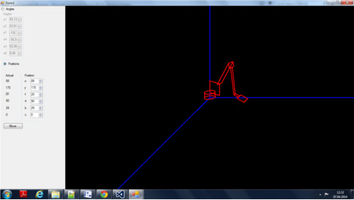
The GUI gives you two series of numeric Up and down control. With the first you can variate the angles of the motors. With the second series, you can give the target position. In the labels, you find the actual position. The actual positions, was more hard as I thought to find. At least I used brute force. Each combination of therm.
For export I think interests you the class Robot. The class Robot, is studied to draw the image. When you ask him, he will give you back a image.
For use it:
Robot^ r;
...
r=gcnew Robot(pictureBox1->Width, pictureBox1->Height);
pictureBox1->Image = r->GetImage();
r->Resize(pictureBox1->Width, pictureBox1->Height);
pictureBox1->Image = r->GetImage();
r->MoveToMotorAngles((double)nA1->Value*dToR,
(double)nA2->Value*dToR,
(double)nA3->Value*dToR,
(double)nA4->Value*dToR,
(double)nA5->Value*dToR,
(double)nA6->Value*dToR);
pictureBox1->Image = r->GetImage();
tuple^ p;
p=r->MoveToPositions((double)nX->Value,
(double)nY->Value,
(double)nZ->Value,
(double)nA->Value*dToR,
(double)nB->Value*dToR,
(double)nC->Value*dToR);
pictureBox1->Image = r->GetImage();
tuple^ p = r->GetPosition();
I did not make the study of geometry, now it can assume unreal geometries, with auto-intersect. I leaved this problem so that you can self understand what are the real problems of a robot, and consequently put the opportune limits, to avoid that your real robot, will destroy him-self, with wrong angles. You have just to put a limit at the angles, and check if possible with another configuration.
This member has not yet provided a Biography. Assume it's interesting and varied, and probably something to do with programming.


 General
  News
News  Suggestion
  Question
  Bug
Bug  Answer
  Joke
Joke  Praise
  Rant
Rant  Admin
Admin 


