Introduction
Many moons ago I used to do embedded programming for the automotive industry and really enjoyed it, but the time came that I had to make a career decision. I decided that there would be a better opportunity in other areas and moved to a location that I believed would afford me that chance. Many years have passed since, but about a year ago, I started seeing articles on micro controllers and embedded programming here on CodeProject and after corresponding with a couple of the authors, I decided that I would like to try and get back into the field I had abandoned so many years ago.
Setup
Once I decided on the hardware platform I was going to use, the next step was to set up the development environment. I researched and downloaded quite a few IDEs and for one reason or another, most just didn't give me that warm fuzzy until I discovered the AVR Studio IDE available [here]. It was the closest thing I could find that worked for me. AVR Studio along with the WinAVR tool chain provide the tools necessary to program in the C and ASM languages, and this is the part I really like: they are both free. The IDE provides one of the best debugging environments of all the IDEs I evaluated, and along with the AVR Dragon I purchased for $50 that does in circuit programming and debugging, I'm in hog heaven. As a side note, the AVR Dragon is one heck of a tool; get it [here].
Hardware
A common activity that you will likely run into when doing embedded programming is the need to scan a keypad, keyboard, or some kind of switch matrix, and as you will find the number of ports or lines needed to scan, these can add up very quickly, so what I am presenting in this article is a way to scan any size matrix type device using only 5 general purpose ports on the micro controller and just a few components. The hardware for this solution is controller independent, and the software can be modified to run on any processor that has general purpose I/O port capability.
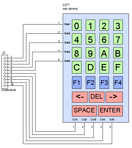
For this project, I purchased a very inexpensive keypad from BGMicro that can be purchased [here] for the paltry sum of $5.10 USD and whose schematic representation is shown in the image that follows. The actual keypad is very similar in appearance to that shown in the image.
To build the hardware for this project, we just need: one serial to parallel shift register, I am using the 74HC595; one parallel to serial shift register, in this case the 74LS165 and 8 X 10K ohm resisters. I won't go into the specifics of how the shift registers operate, but will instead refer you to an excellent article written by a a fellow CPian, DaveAuld, that can be found [here].
The current implementation shown in the schematic that follows is suitable for up to an 8X8 matrix, but can be extended by daisy chaining the shift registers together in any configuration desired. The connector on the left of the schematic is wired to the micro controller and is not shown for brevity, but as stated earlier, may be any controller with 5 available general purpose ports. The connector on the right in the schematic is for the experimenters keypad that I am using.

Let's take a little closer look at the connector on the left in the schematic above that interfaces with the controller; the table that follows defines how each line is used.
| Pin | Description |
|---|
| 5 | Clock line |
| 4 | Data input line from the 74LS165 |
| 3 | Data output line to the 74HC595 |
| 2 | 74HC595 Latch - data output to parallel pins |
| 1 | 74LS165 Load - data input from parallel pins |
The 74HC595 serial in the parallel out shift register is used to pull the column lines to a high logic level one by one. As each column is pulled high, the 74LS165 parallel in serial out shift register loads the current row data in and shifts it out to the controller where it is checked to see if any of the lines are at a high positive level indicating that a key has been pressed. I originally had left out the resistor pack but learned a valuable lesson here about floating inputs and it didn't take me long to realize that the resistors were needed to pull the lines to a defined state. As a side note, the resistor pack may be replaced by individual 10K resistors; I just happened to have a resistor pack in stock.
As can be seen in the schematic above, the clock pin of both devices is tied together and is possible because the 74HC595 is being used as an output device and the 74LS165 as an input device so they do not interfere with each other. Also, the individual devices Latch and Load the data independently so this provides further independence.
The only thing remaining is a way to view the results of the scan; this can be done in any fashion you see fit and that your controller is capable of. In my case, I took advantage of the on chip UART feature and used TeraTerm on the PC to view the results.
Firmware
As I stated at the beginning of this article, I am using the WinAVR gcc "C" complier and the AVR studio IDE to create the firmware for this project. There's not a lot I can say about the firmware without doing a show and tell, so that's what we will do in this section.
We start out by defining what posts we will be using for the interface between the controller and the shift registers; see the connector table for a definition of each of the lines.
#define CMD_PORT DDRC
#define DATA_PORT PORTC
#define PIN_PORT PINC
#define CLOCK PC5
#define MISO PC4 //Master In Slave Out
#define MOSI PC3 //Master Out Slave In
#define LATCH PC2
#define LOAD PC1
static char buffer[] = "Pressed: x";
static char scan_table[5][5] = { { '<', '0', '1', '2', '3' },
{ 'D', '4', '5', '6', '7' },
{ '>', '8', '9', 'A', 'B' },
{ 'E', 'C', 'D', 'E', 'F' },
{ 'S', 'W', 'X', 'Y', 'Z' }};
typedef unsigned char byte;
typedef union ushort
{
uint16_t Short;
uint8_t Byte[2];
} ushort;
This table represents the actual scan codes for this particular keypad and is only given here for those using this keypad and alternately as a reference:
This is the main loop in the main routine and since this application does nothing else but service the keypad, we just poll and wait.
while(1)
{
result = scan();
if (result.Short > 0)
{
row = convert_result(result.Byte[0]);
col = convert_result(result.Byte[1]);
chr = scan_table[col][row];
buffer[9] = chr;
SendDataPacket(buffer, 10);
}
_delay_ms(200);
}
The listing below is the heart of the code and its purpose is to make one complete scan of the keypad by using a mask to pull each column high one by one and shift in the row data checking it for a key press. If there is, then the processing is done and the press is decoded and the scan_code value returned to the main routine.
ushort scan()
{
byte col_mask = 0x80;
byte last_col = 0x04;
volatile byte row = 0;
ushort scan_code;
scan_code.Short = 0;
for(byte i = 0; i < 8; i++)
{
output_data(col_mask);
row = input_data();
if (result != 0)
{
scan_code.Byte[0] = row;
scan_code.Byte[1] = col_mask;
break;
}
if (col_mask == last_col)
col_mask = 0x80;
else
col_mask >>= 1;
}
return scan_code;
}
This routine is used to clock data out to the 74HC595 shift register, and reading through the code, we first bring the Latch to a low level, effectively disabling the output. Contents of the shift register are transferred to output latches on the rising edge so when we are done shifting out our data, we bring this line high. To transfer the data, we start with the most significant bit and set the output port appropriately, toggling the clock after each bit is set, this is called bit banging and is a pretty common practice. If we had used the SPI interface provided on the ATMega328, all we would have had to do was to set the SPI data port with the byte value and wait for it to complete; all shifting is done automatically and has various options that can be set as to whether to send the MSB or LSB first, clock on rising or falling edges, etc..
void output_data(byte data)
{
DATA_PORT &= ~_BV(LATCH);
for (byte i = 0; i < 8;i++)
{
if ((data & 0x80) == 0x80)
DATA_PORT |= _BV(MOSI);
else
DATA_PORT &= ~_BV(MOSI);
DATA_PORT &= ~_BV(CLOCK);
DATA_PORT |= _BV(CLOCK);
data <<= 1;
}
DATA_PORT |= _BV(LATCH);
}
To input the row data, we use similar logic to that used to shift it out, but in this case, we read the value bit by bit and shift it into the result to be returned.
byte input_data()
{
volatile byte result = 0;
DATA_PORT &= ~_BV(LOAD);
DATA_PORT |= _BV(LOAD);
for (byte i = 0; i < 8;i++)
{
result <<= 1;
if ((PINC & 0x10) == 0x10)
result |= 0x01;
DATA_PORT &= ~_BV(CLOCK);
DATA_PORT |= _BV(CLOCK);
}
return result;
}
This final routine is used to convert the scan code to a value that can be used to do a lookup to retrieve the keypad code.
byte convert_result(byte data)
{
byte value = 0;
do
{
if (data & 1)
break;
++value;
data >>= 1;
} while(value < 8);
return value;
}
Conclusion
Shift registers are handy little devices and I have just recently started uncovering their full potential. Used in this application, these two types of shift registers play very nicely together and serve to provide a solution to reduce the number of pins needed to scan a keypad. I've learned a lot from this project, and with every step it becomes a little easier to understand how components may be used like building blocks that you can combine to create or solve a particular problem.
Currently enjoying retirement and working on projects without pressure, deadlines or any kind of management.


