Introduction
The Rodney Robot project is a hobbyist robotic project to design and build an autonomous house-bot using ROS (Robot Operating System). This article is the sixth in the series describing the project.
Background
In part 1, to help define the requirements for our robot, we selected our first mission and split it down into a number of Design Goals to make it more manageable.
The mission was taken from the article, Let's build a robot! and was: Take a message to... - Since the robot will [have] the ability to recognize family members, how about the ability to make it the 'message taker and reminder'. I could say 'Robot, remind (PersonName) to pick me up from the station at 6pm'. Then, even if that household member had their phone turned on silent, or was listening to loud music or (insert reason to NOT pick me up at the station), the robot could wander through the house, find the person, and give them the message.
The design goals for this mission were:
- Design Goal 1: To be able to look around using the camera, search for faces, attempt to identify any people seen and display a message for any identified
- Design Goal 2: Facial expressions and speech synthesis. Rodney will need to be able to deliver the message
- Design Goal 3: Locomotion controlled by a remote keyboard and/or joystick
- Design Goal 4: Addition of a laser ranger finder or similar ranging sensor used to aid navigation
- Design Goal 5: Autonomous locomotion
- Design Goal 6: Task assignment and completion notification
In the last part, we added motor control and odometry feedback to complete Design Goal 3. In this part, I'm going to add a spinning LIDAR (light detection and ranging) to complete Design Goal 4 and add an IMU to improve the odometry. In the process of adding the IMU, I'm also going to replace the Arduino Nano with a Teensy 3.5.
Adding a LIDAR
The most common method for autonomous navigation in ROS requires topic subscription to both the /scan and /tf topics. The /tf topic is used to obtain the odom transform and we started to broadcast this from the ekf_localization_node in the last article. The /scan topic contains data from a laser scan device.
You can see some large and very expensive 360 degree scanning devices on autonomous cars that are under development, but as Rodney is going to be confined to the house, we can considerably step down the price range. Slamtec produce a number of spinning LIDARs and their RPLidar A1 is reasonably priced at around £100 (GBP). The RPLidar has a range of 12 meters, gives a full 360 degree scan and uses a serial interface for communication. But wait it gets better, they have even developed a ROS node available for download from the Slamtec GitHub page. We can therefore plug this device straight into our ROS enabled robot and start receiving messages on the /scan topic without having to figure out what serial data it is transmitting.
Below is a photo of the RPLidar installed on Rodney.
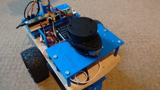
The version of the RPLidar I purchased is the Development Kit and comes with a USB serial device and cable for connecting this device to the LIDAR. As well as the Tx/Rx data lines, it supplies the LIDAR motor and LIDAR core with 5V. There is also a PWM input to the core which can be used to control the speed of the motor, if you use the supplied USB serial device, this line is connected to the DTR signal and can be used to enable/disable the device.
As I'm trying to share the power load between the different supplies I have on Rodney, I decided to supply the motor and the core from different supplies and have only the USB serial device powered from the Raspberry Pi via the USB power. I therefore built a simple breakout board so that I could feed the power to the LIDAR separately. The image below shows this breakout board and the USB serial device mounted on the rear of the platform where the LIDAR is installed. The separate power comes in on the 3 pins which are not connected in the photo. The stl files for the platform and standoffs are available in the 3D print zip file included with this article.

Now some of you who have been following these articles from the start may have spotted a problem. Although I have mounted the RPLidar high enough so that the electronics on the rear platform are below its laser, Rodney's neck is going to be in the way of the laser and thus always result in detection in the 360 degree field. There is available an existing ROS package called laser filters which will allow us to use a plugin called LaserScanAngularBoundsFilter to remove the points from the message covering the neck area. We will use it to remove 10 degrees either side of the 180 degree mark.
To add the code for the RPLidar, we are going to edit some of the packages created in the previous parts of this article, namely rodney and rodney_missions.
The laser filter node will be launched from our rondey.launch file and will require a configuration file which we will load into the ROS parameter server. We therefore need to add the following file named laser_filter_config.yaml to the rodney/config folder.
scan_filter_chain:
- name: angle
  type: laser_filters/LaserScanAngularBoundsFilter
  params:
    lower_angle: -2.96706
    upper_angle: 2.96706
The lower and up angles are in radians which will restrict our field from 0 to -170 and 0 to +170 degrees.
To load these parameters onto the parameter server and to start the scan filter, we will add the following lines to our rodney.launch file in the rodney/launch folder. We are going to be making more changes to the launch file so I'll show it in its entirety later in this article.
<node pkg ="laser_filters" type="scan_to_scan_filter_chain"
 name="scan_to_scan_filter_chain" output="screen">
  <rosparam command="load" file="$(find rodney)/config/laser_filter_config.yaml"/>
  <remap from="scan" to="scan_filter_input"/>
  <remap from="scan_filtered" to="scan"/>
</node>
You can see from the above that we needed to do some remapping of the topic names, the output topic of the node is scan_filtered, but the navigation packages will be subscribing to scan. We will also be remapping the RPLidar published topic from scan to scan_filter_input.
Next we need to launch the RPLidar node provided by Slamtec. A slight problem here is that the serial device provided is identified by the Linux system as /dev/ttyUSBn. This is a common name and can be confusing to the system if you have more than one device with the ttyUSBn name.
We can avoid this uncertainty by adding some udev rules which will create a set of symbolic links which we will use in the launch file. In the rodney/scripts folder, I have created the udev rules in the rodney_udev.rules file.
# Set the udev rules.
#
# Arduino Nano
KERNEL=="ttyUSB*", ATTRS{idVendor}=="1a86", ATTRS{idProduct}=="7523", MODE:="0777", SYMLINK+="nano"
#
# Teensy
KERNEL=="ttyACM*", ATTRS{idVendor}=="16c0", ATTRS{idProduct}=="0483", MODE:="0777", SYMLINK+="teensy"
#
# RPLidar
KERNEL=="ttyUSB*", ATTRS{idVendor}=="10c4", ATTRS{idProduct}=="ea60", MODE:="0777", SYMLINK+="rplidar"
Using a sudo copy command, copy this file to the /etc/udev/rules.d folder on the Raspberry Pi. I have also created a script file called create_udev_rules.sh, which will do the copying for you.
Next, we can add the command to launch the RPLidar node to the rodey.launch file.
<node pkg="rplidar_ros" type="rplidarNode" name="rplidar_node" output="screen">
  <param name="serial_port" type="string" value="/dev/rplidar"/>
  <param name="serial_baudrate" type="int" value="115200"/>
  <param name="frame_id" type="string" value="laser"/>
  <remap from="scan" to="scan_filter_input"/>
</node>
We will build and run all the code in the "Using the Code" section later in the article, but the image below shows the laser scan message visualised in rviz.
IMU (Inertial Measurement Unit)
In part 5, we started to broadcast raw odometry data derived from the motor encoders and included the ekf_localization_node which we said would be used to fuse the raw odometry with IMU data to improve the odometry of the robot.
For the IMU, we are going to use a SparkFun MPU-9250 breakout board.
I want to connect the IMU to the microcontroller and not directly to the Raspberry Pi. As the Arduino Nano is already running out of memory, we need an alternative solution. You could add a second Nano to the project or use one of the larger Arduino boards, but I have decided on my project I'm going to replace the Nano with a Teensy 3.5. Teensy's are faster and contain much more memory than Arduino's, but are compatible with Arduino software and libraries. You can download a plugin so that you can continue to use the Arduino IDE for development. I chose a Teensy 3.5 as unlike the faster 3.6, the digital inputs are 5V tolerant.
The image below shows the IMU (MPU-9250 breakout board) in the lower part of the image and the Teensy is shown top left.
Updates to the Arduino Sketch
Since the Teensy is faster, we will also take the opportunity to increase the baud rate of the serial interface to the Raspberry Pi. As the robot develops, we may also require larger message between the Teensy and the Pi. In order to make the changes to the buffer sizes and baud rate, you need to make changes to the ros.h and ArduinoHardware.h files which are part of the ROS serial library. You could make the changes directly in the library but you would then subsequently lose the changes if you recompiled the library, for example, if you added a new message to the library. I have therefore recreated these files within the sketch folder.
The sketch still incudes the code for the servos and the hall sensors but has been updated to include the IMU functionality.
In the setup function, we now also ensure we can talk to the IMU and call setup procedures from the SparkFun MPU-9250 9 DOF IMU Breakout library which I installed into the Arduino IDE with the Library Manager. Note here that we also setup the magnetometer part of the IMU although we are not currently broadcasting the mag data on any topic. At the end of the setup function, we now only turn on the on-board LED if we successfully setup the IMU.
In the loop function, I have added code to log a message if we failed to set up the IMU. In the past, I found that any log calls made in the setup part of the sketch don't get logged. During each call to loop, we check to see if the IMU registers contain new data, if so we read the accelerometer, gyro and magnetometer data. If it's time to publish the IMU data, we form a sensor_msgs/Imu message and broadcast it on the imu/data_raw topic.
rodney_control.ino
#include <PWMServo.h> // Use PWMServo on Teensy
#include <MPU9250.h>
#include "ros.h"
#include <servo_msgs/servo_array.h>
#include <tacho_msgs/tacho.h>
#include <sensor_msgs/Imu.h>
#include <sensor_msgs/MagneticField.h>
void servo_cb( const servo_msgs::servo_array& cmd_msg);
void WheelSpeed0();
void WheelSpeed1();
#define LED_PIN 13 // Onboard LED
#define GEAR_BOX_COUNTS_PER_REV 1440.0f
#define TACHO_PERIOD_MS 50 // Publish at 20Hz
#define SERVO_0 23
#define SERVO_1 22
#define SERVO_2 21
#define SERVO_3 20
#define ENCODER0_PINA 0 // Interrupt
#define ENCODER0_PINB 1 // Digital pin
#define ENCODER1_PINA 3 // Interrupt
#define ENCODER1_PINB 4 // Digital pin
PWMServo servo0;
PWMServo servo1;
PWMServo servo2;
PWMServo servo3;
#define G_TO_MS2 9.80665
#define I2Cclock 400000
#define I2Cport Wire
#define MPU9250_ADDRESS MPU9250_ADDRESS_AD0
MPU9250 myIMU(MPU9250_ADDRESS, I2Cport, I2Cclock);
tacho_msgs::tacho tachoMsg;
sensor_msgs::Imu imuMsg;
ros::NodeHandle nh;
ros::Publisher tachoPub("tacho", &tachoMsg);
ros::Publisher imuPub("imu/data_raw", &imuMsg);
ros::Subscriber<servo_msgs::servo_array> subServo("servo", servo_cb);
bool imuTestPassed;
byte encoder0PinALast;
byte encoder1PinALast;
volatile int encoder0Count; volatile int encoder1Count; volatile boolean encoder0Direction; volatile boolean encoder1Direction; unsigned long publisherTime;
unsigned long currentTime;
unsigned long lastTime;
char imu_link[] = "imu";
void setup()
{
Wire.begin();
nh.initNode();
nh.advertise(tachoPub);
nh.advertise(imuPub);
nh.subscribe(subServo);
servo0.attach(SERVO_0); servo1.attach(SERVO_1);
servo2.attach(SERVO_2);
servo3.attach(SERVO_3);
servo0.write(90);
servo1.write(120);
servo2.write(90);
servo3.write(90);
encoder0Direction = true; encoder1Direction = true;
encoder0Count = 0;
encoder1Count = 0;
pinMode(ENCODER0_PINB, INPUT);
pinMode(ENCODER1_PINB, INPUT);
attachInterrupt(digitalPinToInterrupt(ENCODER0_PINA), WheelSpeed0, CHANGE);
attachInterrupt(digitalPinToInterrupt(ENCODER1_PINA), WheelSpeed1, CHANGE);
imuTestPassed = true;
byte c = myIMU.readByte(MPU9250_ADDRESS, WHO_AM_I_MPU9250);
if(c == 0x71) {
myIMU.MPU9250SelfTest(myIMU.selfTest);
for(int i = 0; i < 6; i++)
{
if(abs(myIMU.selfTest[i]) > 14.0f)
{
imuTestPassed = false;
}
}
myIMU.calibrateMPU9250(myIMU.gyroBias, myIMU.accelBias);
myIMU.initMPU9250();
byte d = myIMU.readByte(AK8963_ADDRESS, WHO_AM_I_AK8963);
if(d == 0x48)
{
myIMU.initAK8963(myIMU.factoryMagCalibration);
myIMU.getAres();
myIMU.getGres();
myIMU.getMres();
}
else
{
imuTestPassed = false;
}
}
else
{
imuTestPassed = false;
}
if(imuTestPassed == true)
{
pinMode(LED_PIN, OUTPUT);
digitalWrite(LED_PIN, HIGH);
}
}
void loop()
{
static bool setup = false;
if(setup == false)
{
nh.loginfo("Teensy code started");
if(imuTestPassed == false)
{
nh.loginfo("IMU self test failed");
}
setup = true;
}
if(millis() > publisherTime)
{
float deltaTime;
currentTime = micros();
deltaTime = (float)(currentTime - lastTime)/1000000.0;
tachoMsg.rwheelrpm =
(((((float)encoder0Count)/2.0f)/deltaTime)/GEAR_BOX_COUNTS_PER_REV)*60.0f;
encoder0Count = 0;
tachoMsg.lwheelrpm =
(((((float)encoder1Count)/2.0f)/deltaTime)/GEAR_BOX_COUNTS_PER_REV)*60.0f;
encoder1Count = 0;
lastTime = currentTime;
tachoPub.publish(&tachoMsg);
publisherTime = millis() + TACHO_PERIOD_MS;
}
if(imuTestPassed == true)
{
if (myIMU.readByte(MPU9250_ADDRESS, INT_STATUS) & 0x01)
{
myIMU.readAccelData(myIMU.accelCount);
myIMU.ax = (float)myIMU.accelCount[0] * myIMU.aRes;
myIMU.ay = (float)myIMU.accelCount[1] * myIMU.aRes;
myIMU.az = (float)myIMU.accelCount[2] * myIMU.aRes;
myIMU.readGyroData(myIMU.gyroCount);
myIMU.gx = (float)myIMU.gyroCount[0] * myIMU.gRes;
myIMU.gy = (float)myIMU.gyroCount[1] * myIMU.gRes;
myIMU.gz = (float)myIMU.gyroCount[2] * myIMU.gRes;
myIMU.readMagData(myIMU.magCount);
myIMU.mx = (float)myIMU.magCount[0] * myIMU.mRes
* myIMU.factoryMagCalibration[0] - myIMU.magBias[0];
myIMU.my = (float)myIMU.magCount[1] * myIMU.mRes
* myIMU.factoryMagCalibration[1] - myIMU.magBias[1];
myIMU.mz = (float)myIMU.magCount[2] * myIMU.mRes
* myIMU.factoryMagCalibration[2] - myIMU.magBias[2];
}
myIMU.delt_t = millis() - myIMU.count;
if (myIMU.delt_t > 50)
{
imuMsg.header.frame_id = imu_link;
imuMsg.header.stamp = nh.now();
imuMsg.orientation_covariance[0] = -1;
imuMsg.angular_velocity.x = myIMU.gx * DEG_TO_RAD;
imuMsg.angular_velocity.y = myIMU.gy * DEG_TO_RAD;
imuMsg.angular_velocity.z = myIMU.gz * DEG_TO_RAD;
imuMsg.angular_velocity_covariance[0] = 0.003;
imuMsg.angular_velocity_covariance[4] = 0.003;
imuMsg.angular_velocity_covariance[8] = 0.003;
imuMsg.linear_acceleration.x = myIMU.ax * G_TO_MS2;
imuMsg.linear_acceleration.y = myIMU.ay * G_TO_MS2;
imuMsg.linear_acceleration.z = myIMU.az * G_TO_MS2;
imuMsg.linear_acceleration_covariance[0] = 0.1;
imuMsg.linear_acceleration_covariance[4] = 0.1;
imuMsg.linear_acceleration_covariance[8] = 0.1;
imuPub.publish(&imuMsg);
myIMU.count = millis();
}
}
nh.spinOnce();
}
void servo_cb( const servo_msgs::servo_array& cmd_msg)
{
switch(cmd_msg.index)
{
case 0:
servo0.write(cmd_msg.angle); break;
case 1:
servo1.write(cmd_msg.angle); break;
case 2:
servo2.write(cmd_msg.angle); break;
case 3:
servo3.write(cmd_msg.angle); break;
default:
nh.logdebug("Error incorrect servo index");
break;
}
}
void WheelSpeed0()
{
int state = digitalRead(ENCODER0_PINA);
if((encoder0PinALast == LOW) && (state == HIGH))
{
int val = digitalRead(ENCODER0_PINB);
if(val == LOW && encoder0Direction)
{
encoder0Direction = false; }
else if (val == HIGH && !encoder0Direction)
{
encoder0Direction = true; }
}
encoder0PinALast = state;
if(!encoder0Direction)
{
encoder0Count++;
}
else
{
encoder0Count--;
}
}
void WheelSpeed1()
{
int state = digitalRead(ENCODER1_PINA);
if((encoder1PinALast == LOW) && (state == HIGH))
{
int val = digitalRead(ENCODER1_PINB);
if(val == LOW && encoder1Direction)
{
encoder1Direction = false; }
else if (val == HIGH && !encoder1Direction)
{
encoder1Direction = true; }
}
encoder1PinALast = state;
if(!encoder1Direction)
{
encoder1Count++;
}
else
{
encoder1Count--;
}
}
ros.h
#ifndef _ROS_H_
#define _ROS_H_
#include <dummy.h>
#include <ros/node_handle.h>
#include "ArduinoHardware.h"
namespace ros
{
#if defined(__MK64FX512__) || defined(__MK66FX1M0__)
typedef NodeHandle_<ArduinoHardware, 25, 25, 512, 512> NodeHandle;
#elif defined(__AVR_ATmega328P__)
typedef NodeHandle_<ArduinoHardware, 10, 15, 128, 256> NodeHandle;
#else
typedef NodeHandle_<ArduinoHardware> NodeHandle; #endif
}
#endif
ArduinoHardware.h
#ifndef ROS_ARDUINO_HARDWARE_H_
#define ROS_ARDUINO_HARDWARE_H_
#if ARDUINO>=100
#include <Arduino.h> // Arduino 1.0
#else
#include <WProgram.h> // Arduino 0022
#endif
#if defined(__MK20DX128__) || defined(__MK20DX256__) ||
defined(__MK64FX512__) || defined(__MK66FX1M0__) || defined(__MKL26Z64__)
#if defined(USE_TEENSY_HW_SERIAL)
#define SERIAL_CLASS HardwareSerial // Teensy HW Serial
#else
#include <usb_serial.h> // Teensy 3.0 and 3.1
#define SERIAL_CLASS usb_serial_class
#endif
#elif defined(_SAM3XA_)
#include <UARTClass.h> // Arduino Due
#define SERIAL_CLASS UARTClass
#elif defined(USE_USBCON)
#define SERIAL_CLASS Serial_
#elif (defined(__STM32F1__) and !(defined(USE_STM32_HW_SERIAL))) or defined(SPARK)
#define SERIAL_CLASS USBSerial
#else
#include <HardwareSerial.h> // Arduino AVR
#define SERIAL_CLASS HardwareSerial
#endif
class ArduinoHardware {
public:
#if defined(__MK64FX512__) || defined(__MK66FX1M0__)
ArduinoHardware(SERIAL_CLASS* io , long baud= 500000){
iostream = io;
baud_ = baud;
}
ArduinoHardware()
{
#if defined(USBCON) and !(defined(USE_USBCON))
iostream = &Serial1;
#elif defined(USE_TEENSY_HW_SERIAL) or defined(USE_STM32_HW_SERIAL)
iostream = &Serial1;
#else
iostream = &Serial;
#endif
baud_ = 500000;
}
#else // Not a Teensy
ArduinoHardware(SERIAL_CLASS* io , long baud= 57600){
iostream = io;
baud_ = baud;
}
ArduinoHardware()
{
#if defined(USBCON) and !(defined(USE_USBCON))
iostream = &Serial1;
#elif defined(USE_TEENSY_HW_SERIAL) or defined(USE_STM32_HW_SERIAL)
iostream = &Serial1;
#else
iostream = &Serial;
#endif
baud_ = 57600;
}
#endif // defined(__MK64FX512__) || defined(__MK66FX1M0__)
ArduinoHardware(ArduinoHardware& h){
this->iostream = h.iostream;
this->baud_ = h.baud_;
}
void setBaud(long baud){
this->baud_= baud;
}
int getBaud(){return baud_;}
void init(){
#if defined(USE_USBCON)
delay(3000);
#endif
iostream->begin(baud_);
}
int read(){return iostream->read();};
void write(uint8_t* data, int length){
for(int i=0; i<length; i++)
iostream->write(data[i]);
}
unsigned long time(){return millis();}
protected:
SERIAL_CLASS* iostream;
long baud_;
};
#endif
Serial Node Baud Rate
In the ArduinoHardware.h file, we have changed the baud rate of the serial port to 500000 baud. We need to reflect this change at the Raspberry Pi end when we launch the ROS serial node. I have made another change to the rodney.launch file to set the baud rate.
 !-- Teensy.
     Use the defaults /dev/ttyACM0 (or teensy if dev rules updated) and 500000 -->
<arg name="serial_port" default="/dev/teensy"/>
<arg name="baud_rate" default="500000"/>
<node pkg="rosserial_python" type="serial_node.py" name="serial_node" output="screen">
  <param name="port" value="$(arg serial_port)"/>
  <param name="baud" value="$(arg baud_rate)"/>
</node>
IMU Calibration
When we set up the IMU, it includes loading some factory calibration values but we can improve the IMU data by including extra calibration.
For this, we are going to use a ROS package available from this GitHub site. We will also fork the repository and make some code changes of our own. The unchanged package contains two nodes. The first of these computes the accelerometer calibration parameters and saves them to a YAML file. We only need to run this once and as we have to place the IMU into the six orientations with fairly accurate positioning, it is best to do this before fitting the IMU to the robot. The second node uses the calibration file created by the first to apply the calibration to an uncalibrated IMU topic to produce a calibrated IMU topic. The second node can also optionally calculate the gyro biases at startup and then subtract these values from the raw data. Although the setup of the IMU inside the sketch also does this, I found that I received better results if this option was enabled.
In addition, I'm going to add a change to the second node. Although we will have calibrated the IMU, once installed on the robot, it may not be exactly perpendicular to the ground. This will result in accelerometer drift. Now as I only expect to use Rodney in the home and don't expect him to climb or descend any inclines, we can also null out this offset.
To carry out the one time calibration and in order to get the IMU into a fairly accurate position along each of its axes, I installed it into a calibration cube which I 3D printed. Although the cube was for a different model of IMU with a little bit of filling, I was able to install my IMU.
The image shows the IMU installed in the calibration cube. The IMU is being controlled from a spare Teensy but you can use the one installed in the robot.
The calibration node do_calib expects the IMU data to be broadcast in the topic imu. To launch the ROS serial node and to remap the topic, I have created a launch file, cal_imu.launch which is in the rodney/launch folder.
="1.0"
<launch>
<arg name="serial_port" default="/dev/ttyACM0"/>
<arg name="baud_rate" default="500000"/>
<node pkg="rosserial_python" type="serial_node.py"
name="serial_node" output="screen">
<param name="port" value="$(arg serial_port)"/>
<param name="baud" value="$(arg baud_rate)"/>
<remap from="/imu/data_raw" to="imu"/>
</node>
</launch>
Once the serial node is running, in another terminal, type the following command:
$ rosrun imu_calib do_calib
You then follow the instructions given on the terminal. Once the calibration file is produced, copy it to the rodney/config folder.
The changes I have made to the imu_calib package are confined to the apply_calib .cpp and .h files.
To the constructor, I added the reading of parameters from the parameters server so that this functionality can be enabled or disabled.
nh_private.param<bool>("null_accelerometer", null_accelerometer_, true);
nh_private.param<int>("null_accelerometer_samples", null_accelerometer_samples_, 100);
In the function rawImuCallback, I added code to calculate the mean accelerometer offsets at startup.
if(null_accelerometer_ == true)
{
ROS_INFO_ONCE("Nulling accelerometer; do not move the IMU");
sensor_msgs::Imu corrected = *raw;
accel_sample_count_++;
calib_.applyCalib(raw->linear_acceleration.x,
raw->linear_acceleration.y, raw->linear_acceleration.z,
&corrected.linear_acceleration.x, &corrected.linear_acceleration.y,
&corrected.linear_acceleration.z);
accel_bias_x_ = ((accel_sample_count_ - 1) *
accel_bias_x_ + corrected.linear_acceleration.x) / accel_sample_count_;
accel_bias_y_ = ((accel_sample_count_ - 1) *
accel_bias_y_ + corrected.linear_acceleration.y) / accel_sample_count_;
accel_bias_z_ = ((accel_sample_count_ - 1) * accel_bias_z_ +
(corrected.linear_acceleration.z-9.80665)) / accel_sample_count_;
if (accel_sample_count_ >= null_accelerometer_samples_)
{
ROS_INFO("Nulling accelerometers complete! (bias = [%.3f, %.3f, %.3f])",
accel_bias_x_, accel_bias_y_, accel_bias_z_);
null_accelerometer_ = false;
}
}
These values are then subtracted from the calibration corrected values.
corrected.linear_acceleration.x -= accel_bias_x_;
corrected.linear_acceleration.y -= accel_bias_y_;
corrected.linear_acceleration.z -= accel_bias_z_;
The updated package is available in the code zip file under the imu_calib folder.
The following was added to the rodney.launch file to launch the updated node and to pass the location of the calibration file.
<node pkg="imu_calib" type="apply_calib" name="imu_calib" output="screen">
<param name="calib_file" value="$(find rodney)/config/imu_calib.yaml"/>
</node>
Now in the previous part of this article, we added the ekf_localization_node from the robot_localization package. This node will fuse the IMU data with the raw odometry data to produce the odometry data which will be used by the navigation system I'll introduce in the next article.
The configuration of this data fusing is contained in the robot_localization.yaml file which can be found in the rodney/config folder. We briefly discussed this file in the last article but it is worth adding some detail here.
The data in the configuration matrix represents the following:
[ x position,     y position,     z position,
  roll,           pitch,          yaw,
  x velocity,     y velocity,     z velocity,
  roll velocity,  pitch velocity, yaw velocity,
  x acceleration, y acceleration, z, acceleration]
A "true" value in the matrix means the data in that position will be used by the Extended Kalman Filter.
Now for the raw odometry data I have:
odom0_config: [false, false, false,
               false, false, false,
               true,  true,  false,
               false, false, true,
               false, false, false]
Although the odometry message also contains the position data, it was derived from the same source as the velocity data so there is no point in using the data twice. It could also be argued that since we always set the y velocity to zero that we could set this matrix value to false. If, however, you want to include the y velocity from the IMU, it helps to cancel drift from the IMU by including this parameters in the odom matrix.
Now there are two different configurations that I have tried for the IMU matrix. Firstly one which uses just the yaw velocity from the IMU data.
imu0_config: [false, false, false,
              false, false, false,
              false, false, false,
              false, false, true,
              false, false, false]
You can also try a configuration which also uses x and y velocity but you need to ensure that you have reduced any noise/error on the data first, or else the odometry will be subject to x and/or y drift.
imu0_config: [false, false, false,
              false, false, false,
              true, true, false,
              false, false, true,
              false, false, false]
Static Transforms
In the last part, we introduced a static transform for the height of the robot base from the ground. This latched transform broadcast was setup from the rodney.launch file with the following:
<node pkg="tf2_ros" type="static_transform_publisher"
      name="base_footprint_broadcaster" args="0 0 0.09 0 0 0 /base_footprint /base_link"/>
Now that we have added the LIDAR and IMU, we need to add more static transforms. Calculations are made from the middle of the robot, so any distances reported in the scan message need to be transformed from the location of the LIDAR to the centre of the robot.
We could add two more static transforms like the one above to the launch file but instead we will remove the existing one and write a simple node, which we will include in the rodney package, to handle all three static transforms.
In the rodney/src folder, I have added the static_broadcaster.py file. This Python script will create a node responsible for broadcasting the three static transforms. This message is latched so nodes that require the transform will be passed the data on startup.
import sys
import rospy
import tf
import tf2_ros
import geometry_msgs.msg
def main(args):
rospy.init_node('rodney_static_broadcaster', anonymous=False)
rospy.loginfo("rodney static broadcaster node started")
broadcaster = tf2_ros.StaticTransformBroadcaster()
st1 = geometry_msgs.msg.TransformStamped()
st1.header.stamp = rospy.Time.now()
st1.header.frame_id = "/base_footprint"
st1.child_frame_id = "/base_link"
st1.transform.translation.x = 0.0
st1.transform.translation.y = 0.0
st1.transform.translation.z = 0.09
quat = tf.transformations.quaternion_from_euler(0.0, 0.0, 0.0)
st1.transform.rotation.x = quat[0]
st1.transform.rotation.y = quat[1]
st1.transform.rotation.z = quat[2]
st1.transform.rotation.w = quat[3]
st2 = geometry_msgs.msg.TransformStamped()
st2.header.stamp = rospy.Time.now()
st2.header.frame_id = "/base_link"
st2.child_frame_id = "/laser"
st2.transform.translation.x = 0.085
st2.transform.translation.y = 0.0
st2.transform.translation.z = 0.107
quat = tf.transformations.quaternion_from_euler(0.0, 0.0, 0.0)
st2.transform.rotation.x = quat[0]
st2.transform.rotation.y = quat[1]
st2.transform.rotation.z = quat[2]
st2.transform.rotation.w = quat[3]
st3 = geometry_msgs.msg.TransformStamped()
st3.header.stamp = rospy.Time.now()
st3.header.frame_id = "/base_link"
st3.child_frame_id = "/imu"
st3.transform.translation.x = 0.0
st3.transform.translation.y = 0.0
st3.transform.translation.z = 0.058
quat = tf.transformations.quaternion_from_euler(0.0, 0.0, 0.0)
st3.transform.rotation.x = quat[0]
st3.transform.rotation.y = quat[1]
st3.transform.rotation.z = quat[2]
st3.transform.rotation.w = quat[3]
broadcaster.sendTransform([st1, st2, st3])
rospy.spin()
if __name__ == '__main__':
main(sys.argv)
The node is started in the rodney.launch file:
<node pkg="rodney" type="static_broadcaster.py" name="static_broadcaster_node"/>
Launch File
Another change I have made to the rodney.launch file is to remove the...
output="screen"
...from each of the nodes which are no longer under development or test. This reduces the log messages displayed in the terminal that we launch the robot code from. However, you can still use rqt_console on a remote terminal to monitor all the log messages.
The full rodney.launch file now looks like this:
="1.0"
<launch>
<node pkg="rodney" type="static_broadcaster.py" name="static_broadcaster_node"/>
<rosparam command="load" file="$(find pan_tilt)/config/config.yaml"/>
<rosparam command="load" file="$(find face_recognition)/config/config.yaml"/>
<rosparam command="load" file="$(find head_control)/config/config.yaml"/>
<rosparam command="load" file="$(find rodney_missions)/config/config.yaml"/>
<include file="$(find raspicam_node)/launch/camerav2_1280x960.launch" />
<node pkg="pan_tilt" type="pan_tilt_node" name="pan_tilt_node"/>
<node pkg="face_recognition" type="face_recognition_node.py" name="face_recognition_node"/>
<node pkg="head_control" type="head_control_node" name="head_control_node"/>
<node pkg="speech" type="speech_node" name="speech_node"/>
<node pkg="rodney_missions" type="rodney_missions_node.py"
name="rodney_missions" output="screen"/>
<node pkg="rodney" type="rodney_node" name="rodney" output="screen">
<rosparam command="load" file="$(find rodney)/config/config.yaml"/>
</node>
<node pkg="thunderborg" type="thunderborg_node.py" name="thunderborg_node">
<rosparam command="load" file="$(find thunderborg)/config/config.yaml"/>
</node>
<arg name="serial_port" default="/dev/teensy"/>
<arg name="baud_rate" default="500000"/>
<node pkg="rosserial_python" type="serial_node.py" name="serial_node" output="screen">
<param name="port" value="$(arg serial_port)"/>
<param name="baud" value="$(arg baud_rate)"/>
</node>
<node pkg="rplidar_ros" type="rplidarNode" name="rplidar_node" output="screen">
<param name="serial_port" type="string" value="/dev/rplidar"/>
<param name="serial_baudrate" type="int" value="115200"/>
<param name="frame_id" type="string" value="laser"/>
<remap from="scan" to="scan_filter_input"/>
</node>
<node pkg ="laser_filters" type="scan_to_scan_filter_chain"
name="scan_to_scan_filter_chain" output="screen">
<rosparam command="load" file="$(find rodney)/config/laser_filter_config.yaml"/>
<remap from="scan" to="scan_filter_input"/>
<remap from="scan_filtered" to="scan"/>
</node>
<node pkg="homer_robot_face" type="RobotFace" name="RobotFace"/>
<node pkg="imu_calib" type="apply_calib" name="imu_calib" output="screen">
<param name="calib_file" value="$(find rodney)/config/imu_calib.yaml"/>
</node>
<node pkg="robot_localization" type="ekf_localization_node" name="ekf_localization_node">
<remap from="odometry/filtered" to="odom"/>
<rosparam command="load" file="$(find rodney)/config/robot_localization.yaml"/>
</node>
</launch>
Minor Code Changes
I have also made some minor changes to the code mostly around being able to enable/disable the LIDAR when the robot is in manual mode and also to ensure we don't get a runaway robot when it is being remotely controlled.
Updates to the rodney_missions Node
I have made small changes so that this node can enable/disable the LIDAR by starting and stopping the LIDAR motor. The request comes from the rodney node but it's important that the control is done here so that this node can ensure the LIDAR is running when in the future, it requests autonomous navigation.
The starting and stopping of the motor is done via ROS service calls to the LIDAR node. The first of the changes are in the __init__ function of the MissionsHelper class. We wait for the services to become available, create proxy calls so that we can access the service and then call the LidarEnable helper function to ensure the LIDAR is currently running.
rospy.wait_for_service('stop_motor')
rospy.wait_for_service('start_motor')
self.__rplidar_stop_motor_srv = rospy.ServiceProxy('stop_motor', std_srvs.srv.Empty)
self.__rplidar_start_motor_srv = rospy.ServiceProxy('start_motor', std_srvs.srv.Empty)
self.LidarEnable()
Next, I have added three helper functions to MissionHelper class. They call the service in question and keep track of the current state of the LIDAR motor.
def LidarEnable(self):
self.__rplidar_start_motor_srv()
self.__lidar_on = True
def LidarDisable(self):
self.__rplidar_stop_motor_srv()
self.__lidar_on = False
def ToggleLidar(self):
if(self.__lidar_on == True):
self.LidarDisable()
else:
self.LidarEnable()
The final change is in the Prepare class and adds a new elif construct to the execute function. If the job received is of id 'J4', then the request is to toggle the current state of the LIDAR.
elif parameters[0] == 'J4':
self.__helper_obj.ToggleLidar()
Updates to the rodney Package
We need to make some changes to the rodney node so that we can use the joystick and/or keyboard attached to the remote workstation to enable/disable the LIDAR when in manual mode.
Also, on occasions when I have been manually controlling the robot, my home network has dropped out for a few seconds. The problem here is that the robot will carry on using the velocities created from the last joystick or keyboard input. I have therefore added a new node (remote_heartbeat_node) to the rodney package which is run on the remote workstation and publishes a heartbeat message. The rodney node running on the robot hardware monitors this message and if the robot is in manual mode and the message is not received for one second, then the velocities will be set to zero.
Changes to the rodney_node.cpp file.
We can now enable/disable the LIDAR from the joystick so we need a way to configure which button controls this functionality. Add the following line to the RodneyNode constructor.
nh_.param("/controller/buttons/lidar_enable", lidar_enable_select_, 2);
In the joystickCallback function, add the following "if" construct to request the LIDAR motor state be toggled if the joystick button in question is pressed.
if((manual_locomotion_mode_ == true) && (msg->buttons[lidar_enable_select_] == 1))
{
std_msgs::String mission_msg;
mission_msg.data = "J4";
mission_pub_.publish(mission_msg);
last_interaction_time_ = ros::Time::now();
}
Likewise if the 'l' key is pressed on the keyboard, the motor state is toggled. Add the following "else if" construct to the keyboardCallBack function.
else if((msg->code == keyboard::Key::KEY_l) &&
((msg->modifiers & ~RodneyNode::SHIFT_CAPS_NUM_LOCK_) == 0))
{
if(manual_locomotion_mode_ == true)
{
std_msgs::String mission_msg;
mission_msg.data = "J4";
mission_pub_.publish(mission_msg);
last_interaction_time_ = ros::Time::now();
}
}
Next, the node needs to subscribe to the new heartbeat message by adding the following to the RodneyNode constructor.
remote_heartbeat_sub_ = nh_.subscribe
                        ("remote_heartbeat", 1, &RodneyNode::remHeartbeatCallback, this);
A callback function for when the message on this topic is received will store the time of the last message.
void RodneyNode::remHeartbeatCallback(const std_msgs::Empty::ConstPtr& msg)
{
remote_heartbeat_time_ = ros::Time::now();
}
In the sendTwist function, we need to set the velocities to zero if it's been more than one second since the last heartbeat message was received. Below is the complete new version of the sendTwist function.
void RodneyNode::sendTwist(void)
{
geometry_msgs::Twist target_twist;
if(manual_locomotion_mode_ == true)
{
if((ros::Time::now() - remote_heartbeat_time_).toSec() < 1.0)
{
if((keyboard_linear_speed_ == 0) && (keyboard_angular_speed_ == 0))
{
target_twist.linear.x = joystick_linear_speed_;
target_twist.angular.z = joystick_angular_speed_;
}
else
{
target_twist.linear.x = keyboard_linear_speed_;
target_twist.angular.z = keyboard_angular_speed_;
}
}
else
{
target_twist.linear.x = 0.0;
target_twist.angular.z = 0.0;
}
}
else
{
target_twist.linear.x = linear_mission_demand_;
target_twist.angular.z = angular_mission_demand_;
}
if (false == pid_enabled_)
{
ros::Time time_now = ros::Time::now();
last_twist_ = rampedTwist(last_twist_, target_twist, last_twist_send_time_, time_now);
last_twist_send_time_ = time_now;
twist_pub_.publish(last_twist_);
}
else
{
twist_pub_.publish(target_twist);
}
}
Next, we will add the remote_heartbeat_node.cpp file to the rodney/src folder. Remember this node will not be run on the robot hardware but on a remote workstation being used to manually drive the robot. This simple node just broadcasts the heartbeat message at 5Hz.
#include <ros/ros.h>
#include <std_msgs/Empty.h>
int main(int argc, char **argv)
{
ros::init(argc, argv, "remote_heartbeat");
ros::NodeHandle n;
ros::Publisher remote_heartbeat_pub = n.advertise<std_msgs::Empty>("remote_heartbeat", 1);
std::string node_name = ros::this_node::getName();
ROS_INFO("%s started", node_name.c_str());
ros::Rate r(5);
std_msgs::Empty beat;
while(ros::ok())
{
remote_heartbeat_pub.publish(beat);
ros::spinOnce();
r.sleep();
}
return 0;
}
One final change to the rodney package is to add a launch file that can be used to launch the keyboard, joystick and heartbeat nodes all together. The file name is remote.launch and it is in the rodney/launch folder.
="1.0"
<launch>
<node pkg="joystick" type="joystick_node" name="joystick_node"/>
<node pkg="keyboard" type="keyboard" name="keyboard"/>
<node pkg="rodney" type="remote_heartbeat_node" name="remote_heartbeat_node" output="screen"/>
</launch>
Robot Hardware
A full size image of the current circuit diagram is available in the diagrams zip folder along with a full size copy of the image from rqt_graph showing all the nodes and topics.
A complete bill of material for the project so far is available here.
In part 1 of the article, I referenced the Ubiquity Robot Image which I use on the Raspberry Pi. Instructions on how to install the image, install extra software and configure it for the project are available here.
Using the Code
As usual, I'll run the code on the robot hardware and run the test tools and manual control nodes on a Linux PC. I'll refer to this PC as the workstation in the details below.
Building the ROS Packages on the Pi (Robot Hardware)
If not already done, create a catkin workspace on the Raspberry Pi and initialise it with the following commands:
$ mkdir -p ~/rodney_ws/src
$ cd ~/rodney_ws/
$ catkin_make
Copy the packages face_recognition, face_recognition_msgs, head_control, imu_calib, pan_tilt, rodney, rodney_missions, ros-keyboard, rplidar-ros, servo_msgs, speech, tacho_msgs and thunderborg into the ~/rodney_ws/src folder.
Build the code with the following commands:
$ cd ~/rodney_ws/
$ catkin_make
Check that the build completes without any errors.
You will also need to compile and download the sketch to the Teensy 3.5.
Building the ROS Packages on the Workstation
On the workstation, we want to run the keyboard, joystick and heartbeat nodes so that we can control the actual robot hardware remotely.
Create a workspace with the following commands:
$ mkdir -p ~/test_ws/src
$ cd ~/test_ws/
$ catkin_make
Copy the packages rodney, joystick, odom_test and ros-keyboard into the ~/test_ws/src folder, and then build the code with the following commands:
$ cd ~/test_ws/
$ catkin_make
Check that the build completes without any errors.
Tip
When running ROS code and tools on a workstation and the Raspberry Pi, there can be a lot of repeat typing of commands at a number of terminals. In the next sections, I have included the full commands to type but here are a few tips that can save you all that typing.
On the Raspberry Pi, to save typing "source devel/setup.bash", I have added it to the .bashrc file for the Raspberry Pi.
$ cd ~/
$ nano .bashrc
Then add "source /home/ubuntu/rodney_ws/devel/setup.bash" to the end of the file, save and exit.
When running test code and tools on the workstation, it also needs to know where the ROS master is so I have added the following to the .bashrc file for the workstation.
alias rodney='source ~/test_ws/devel/setup.bash; \
export ROS_MASTER_URI=http://ubiquityrobot:11311'
Then by just typing "rodney" at a terminal, the two commands are run and a lot of typing is saved.
You can also save some typing as some ROS tools support TAB completion. For example, type rosrun rosserial_ and then press the tab key to auto complete rosrun rosserial_python.
Starting the Code
On the robot hardware, run the following commands to start all the current nodes in the system:
$ source rodney_ws/devel/setup.bash
$ roslaunch rodney rodney.launch
On the workstation, run the following commands to start the remote control nodes:
$ source test_ws/devel/setup.bash
$ export ROS_MASTER_URI=http://ubiquityrobot:11311
$ roslaunch rodney remote.launch
A small window whose title is "ROS keyboard input" should be running. When entering keyboard strokes, ensure the small window has the focus.
In another terminal on the workstation, start rviz with the following commands:
$ source test_ws/devel/setup.bash
$ export ROS_MASTER_URI=http://ubiquityrobot:11311
$ roslaunch rodney rviz.launch
Testing the LIDAR
Configure rviz so that the Fixed Frame is base_link and so that LaserScan is displaying the /scan topic. You should see a visual representation of the scan message within rviz.
It should also be possible to use either the joystick controller or keyboard to remotely control the robot avoid obstacles that are picked up by the laser.
In a new terminal on the workstation, enter the following commands to disable to LIDAR:
$ source test_ws/devel/setup.bash
$ export ROS_MASTER_URI=http://ubiquityrobot:11311
$ rosservice call /stop_motor
The LIDAR should stop spinning and the scan display in rviz should not be updated.
In the terminal, enter the following command to enable the LIDAR:
$ rosservice call /start_motor
The LIDAR should start spinning and the scan display in rviz should be updated.
Testing the IMU
To ensure both the raw and fused odometry are zero, close the terminal on the robot hardware that launched the code.
On the robot hardware, re-start with the following commands in a new terminal:
$ source rodney_ws/devel/setup.bash
$ roslaunch rodney rodney.launch
Configure rviz so that:
- the Fixed Frame is
odom - The Transforms (TF)
base_link and odom axes are displayed - The odometry /raw_odom and /odom are displayed in different colours
Mark the position of the robot on the floor. Use the keyboard or joystick to move the robot.
In a terminal on the workstation, type the following to view the current odometry message:
$ source test_ws/devel/setup.bash
$ export ROS_MASTER_URI=http://ubiquityrobot:11311
$ rostopic echo /odom
From the message, note the current pose position, x and y. Measure the distance the robot has moved from the marked position and confirm that it is a good approximation.
Use the keyboard or joystick to rotate the robot. The pose orientation is not so easy to compare as it is a Quaternion. You can see the orientation in rviz, but you can also use the test script odom_test, to confirm the angle in degrees.
In the terminal on the workstation, press Ctrl-C and then enter the following command:
$ rosrun odom_test odom_test1_node.py
Once per second, the node will print out the pose orientation in degrees for both the raw and fused odometry message.
On the rviz display, you will see two sets of arrows showing the raw and fused odometry. Also, when the robot is returned to the place it started, the base_link and odom transforms should be fairly close.
Image shows the trace of the raw odometry (red arrows) and the fused odometry (green arrows):
Points of Interest
In this part, we have completed Design Goal 4 and also added an IMU to improve the odometry.
In the next article, we add packages that use the LIDAR for autonomous navigation, including creating a map from the LIDAR and odom transform data. We will use rviz to set target poses and the robot will autonomously navigate to the set location.
History
- 2019/04/15: Initial release
Having spent the last 40 years as an engineer, 19 years as a test and commissioning engineer and 21 years as a software engineer, I have now retired to walk the Cumbrian fells and paddle the coast and lakes. When the weather is inclement I keep my hand in with robotic software and hardware. Over the years I have used Code Project to help me solve some programming issues so now with time on my hands it’s time to put something back into the Code Project.


