Note: I request you to please vote and provide comments.
Introduction
In my previous article – Understanding Raspberry Pi - GPIO, we talked about GPIO (General Purpose Input Output). In this article, we will discuss a handy tool – Breadboard – It is a must have tool for everyone working on building simple to complex circuits and also, when using Raspberry Pi.
Background
You might be thinking about the name “Breadboard” and wondering if this has anything to do with bread. Well, Yes and No. The name breadboard comes from earlier days of electronic circuits, where people would literally use wooden boards (bread cutting boards) with screws or nails driven into them to make electronic connections. Let's see what a modern Breadboard is.
Modern Breadboards are rectangular pieces of plastic with a Grid of holes, that allow us to quickly and easily build electronic circuits by pushing electronic components in to the holes.
Modern breadboards come in all sizes and shapes and in different colors. Some breadboards are transparent as well. The most common sizes are full-size breadboards, half-size breadboards, and mini breadboards. Also, most of the breadboards come with notches on the side that allows you to snap more than one board together.
Let’s take a closer look at how a bread board works. See the below full size and half size breadboards and also a clear / transparent breadboard.
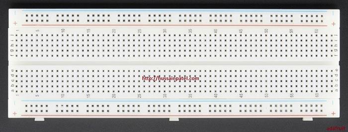
Figure 1. Full-size Breadboard

Figure 2. Small-size breadboard
Figure 3. Small-size breadboard
Figure 4. Clear / Transparent breadboard
The holes on a breadboard allow you to push the lead or metal legs of a component into them and tightly hold them into the place. This connection is strong enough such that the component won’t fall out of its own, but you can easily snap in or snap out a component in case you want to change / replace it from that place.
Breadboard are also called as solderless breadboards (less commonly used name) – because you don’t need to solder to bond the electronic components together.
Now, let’s take a closer look at a full size breadboard. (Figure 5)
Figure 5: Full-size breadboard
In the figure above, you see a full-sized breadboard. On either side of the breadboard are vertical lines or strips usually labeled with a 'red and black' or 'red and blue' lines and also having + or – sign. These lines are called busses or rails and are used to deliver power vertically to the entire circuit. Typically, the holes next to the red line (+) sign will connect to the positive battery terminal and the holes next to the blue line (–) sign will connect to the negative battery terminal.
The two columns on the inside of the breadboard work horizontally. What it means that internally they are wired horizontally and when connected to power, the power flows horizontally along the row of each columns. So, if you look at row 1, the holes marked A, B, C, D, and E are connected and the holes in rows F, G, H, I, and J are connected (i.e., power will from A to E and F to J).
Let's see how this works, with a practical demo.
Demo: Simple LED circuit on a Breadboard
Hardware Components - Breadboard, 1 LED (Red), 1 Resistor 10 ohms, 9 volt battery, battery snap, and 1- Jumper wire (male to male).
Step 1
Take the positive (red) and the negative (black) wires of the battery snap and connect to the top power rails. Take the red wire and insert one end into the hole next to the red line, then take the black wire and insert into the hole next to the blue line.
Figure a.
Step 2
Next, take the LED. Take the long end of the led and insert this into E15 and the short end of the LED into F 45 (Note: Make sure you are inserting the correct leg of the LED, else the LED may not glow and get fused).
Figure b.
Step 3
Next, take the jumper wire and insert one end in to hole C15, 2 holes next to E15, then insert the other end of the jumper wire into the power rail hole 15 (technically, you can insert in any hole on the power rail as the battery power is passing vertically from top to bottom in the power rail).
Figure c.
Step 4
Next, take a resistor and insert this into 2 holes after F45, i.e., H45 and then insert the other end of the resistor into the hole 45 of the power rail (technically, you can insert in any hole on the power rail as the battery power is passing vertically from top to bottom in the power rail).
Figure d.
Step 5
Check the connection once more (Steps 1 to 4). Now, connect the 9 volt battery to the battery snap and the LED should glow.
Figure e.
From the above demo, you can see how to use the breadboard and how easy it is to snap in and snap out components. The breadboard really helps in keeping your components together and quickly tests them as part of a circuit.
References
In the next article, we will talk about setting up Raspberry Pi and installing OS on Raspberry Pi using NOOBS.
Hope this helps!
Happy learning, happy making!
History
- 24th September, 2017: Initial version


 General
  News
News  Suggestion
  Question
  Bug
Bug  Answer
  Joke
Joke  Praise
  Rant
Rant  Admin
Admin 


