Get access to the new Intel® IoT Developer Kit, a complete hardware and software solution that allows developers to create exciting new solutions with the Intel® Galileo and Intel® Edison boards. Visit the Intel® Developer Zone for IoT.
Input and output (I/O) basics are key for getting deeper into prototyping your own Internet of Things device. This article provides the basics of I/O in electronics, with examples of its implementation.
For a circuit to perform a useful action, it must receive data (input) to which it will respond with an action (output). Think of a child’s toy where a press of a button turns a light turns on, and when you release the button, the light turns off. Sensors and actuators come into play to make this possible. Sensors fall under the input role: Their sole function is to sense a variety of changes in the physical world, such as temperature, touch, force, humidity, and magnetic field. Sensors are also referred to as transducers because they convert input energy found in the physical world into output energy. The output function is generally managed by actuators, which control devices such as light bulbs or speakers.
Sensors and Actuators
There are many different types of sensors, and they’re designed according to the energy change they measure. An accelerometer is a sensor commonly found in many projects. Measuring acceleration force, it’s composed of an element such as a beam that is subject to an electrical voltage to cause agitation. Within the accelerometer family you can find various categories depending on how the accelerometer senses the change in acceleration, such as capacitive (change in capacitance related to acceleration), piezoelectric (uses microcrystals to determine voltage output converted to acceleration), Hall effect (changing magnetic fields), magnetoresistive (change in magnetic field), heat transfer, and piezoresistive (change in electrical resistance). When buying a sensor for your project, note that the price may vary depending on the sensitivity, range, precision, and accuracy, among other factors. An actuator gathers the data from the sensor (electrical signal) and acts on it, causing a change in the physical world. It is also a transducer because it changes one type of quantity into another. Servos, motors, and buzzers all fall under the output category. In more complex networks, you can have multiple sensors and actuators connected on one network, where data collection and coordination can be set from sensor to sensor, sensor to actuator, or actuator to actuator.
There are many applications for sensors and actuators. In the health field, a glucometer is equipped with biological sensors that measure the amount of glucose in a patient’s body. A chemical transducer (input) triggers the release of insulin using a micropump (output). Figure 1 shows an I/O scenario in which a sound sensor (input) converts the sound into electrical impulses and a speaker (output) converts such impulses into sound. The flow starts with an input, followed by the process of morphing the physical energy into electrical waves, which leads to a physical output (sound). In Figure 1, the sensor and actuator are connected to an Intel® Edison board, which aids in the conversion of the physical observation of sound into the output the speaker creates.
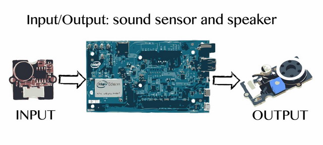
Figure 1. Input and output for sound
When a sensor detects one or more signals (input), it converts those signals to an analog or digital representation for the actuator to receive. Analog changes vary at a continuous rate; their illustration is that of continuous smooth curves. Digital data is of a precise count, creating a step-like graph with sharp ups, constant sections, and sharp downs. In the example in Figure 1, the data is analog. Electronic devices that handle both analog and digital communications count with an analog-to-digital converter, which enables the microcontroller to connect to an analog sensor to read in an analog voltage. Figure 2 provides a visual representation of digital and analog waves. Sensors can be designed with either/or capabilities; in fact, there are both analog and digital accelerometers, whereas light sensors and sound are considered analog.

Figure 2. Digital and analog signal types
Explore Input and Output with an Intel® Edison Board
Let’s look more deeply into what enables the I/O functionality on a board, such as the Intel® Edison board. General-purpose input/output (GPIO) pins are located on the edges of the Arduino* expansion board, as shown of Figure 3. These pins are a physical interface between the physical world and the Intel® Edison board: Each pin can represent a high ("on" state, voltage change) or low ("off" state, no voltage). You can then mount a base shield on the pins to connect sensors and actuators. On the Intel® Edison board, I/O pin data is written on a file located at /sys/class/gpio. Given that the pins are bidirectional, the direction is stated at /sys/class/gpio/gpio<XX>/direction where <XX> represents the number given to enabled GPIO and direction can be either in or out.
Figure 3. Pins on the Intel® Edison board
Now that you have a clear understanding of what I/O is and the role it plays in your projects, let’s look at more concrete examples you might encounter daily and how you can create similar devices by using Intel technology, such as the Intel® Edison or Intel® Galileo board.
Light Sensors
A photo sensor is a passive analog device that converts light energy, whether visible or infrared, into an electrical signal output. Light sensors fall into four types, depending on how they react to the input (light): photoemissive, photoconductive, photovoltaic, and photojunction. This article focuses on photoconductive sensors, which vary their electrical resistance when subjected to light. The increase in light results in an increase in current. A light-dependent resistor (LDR) is a photoconductive sensor commonly used in devices that create an action depending on the presence or lack of light, as determined by the changes its electrical resistance.
Newer cars automatically turn on their lights in the absence of "sufficient" ambient light, such as at dusk or when entering a dark tunnel. Similarly, you can plug nightlights throughout your house or in outdoor areas to illuminate the space. You can create a simple homemade nightlight by using an LDR, a source of power (such as a battery), a light, a resistor, and and transistor. To add functionality, specify actions according to the input in the code loaded onto the Intel® Edison board.
Sound Sensors
The famous "clapper on/off" lights benefit from the use of a sound sensor. The device counts with a microphone that listens to the surrounding noise (input), which it turns into an electrical signal and amplifies. The filter matches claps by identifying which sound falls within a certain frequency. Depending on the outcome of the filter, the artifact will send (or not) an electrical signal to the plug outlet to power on or off the item connected to it.
Using an Intel® Edison board with an Arduino* extension board along with a speaker and some transistors, you can build your own clapper or "knocker," such as the one presented in the "Secret Knock Detecting Door Lock" Instructables project at http://www.instructables.com/id/Secret-Knock-Detecting-Door-Lock.
Summary
You can use sensors to obtain data and combine them with an actuator so that data can result in a transformation of a physical input into a physical output. A wide range of available sensors accommodate diverse use cases and applications, such as thermal sensors, photo sensors, and pressure sensors just to name a few. Connect sensors and actuators to an Intel® Edison board or Intel® Galileo board to obtain data from the sensors and output a result on the actuators.
Additional Reading
Login to leave a comment below. If you are not registered go to the Intel® Developer Zone to sign up.
You may know us for our processors. But we do so much more. Intel invents at the boundaries of technology to make amazing experiences possible for business and society, and for every person on Earth.
Harnessing the capability of the cloud, the ubiquity of the Internet of Things, the latest advances in memory and programmable solutions, and the promise of always-on 5G connectivity, Intel is disrupting industries and solving global challenges. Leading on policy, diversity, inclusion, education and sustainability, we create value for our stockholders, customers and society.


