Table of contents
Introduction
Initial data and condition
Solution
Tile storage
Steps to prepare tiles
Functions to be used
Example of polyline object shape
Intersection detection
Tables to store tile images
Drawing icon on a tile at specific position
Tile combining
Drawing geometry shape on a tile
Conclusion
Introduction
This article is about drawing geometry on geographical tiles. When large amount of icons or shapes are shown on an electronical map in a browser in a vectorized format, for example in SVG or using CANVAS, it consumes a lot of resources on a client machine. So we are going to display them as raster images. We will find out how to fill list of tiles to be rendered. A way of positioning an icon on a tile and drawing graphical primitives on a tile is explored here. It assumes what graphical primitives are stored in the GEOMETRY field of a table in MS SQL database. The whole process of tile rendering for the object shape will be covered step by step with a real example at the end of this article.
Initial data and condition
Subset of geometry shapes are stored in a database of Microsoft SQL 2008. Coordinates of vertices are latitude and longitude [EPSG:4326]. The field with spatial data has GEOMETRY data type. Objects with only one point as a shape (geometry with Point shape type) are shown on a map as icons in PNG format. If an object has a sequence of intercepts, as its shape it is drawn as a polyline with the specified width. In a database it has a shape type of Linestring or Multilinestring. Polygon GEOMETRY is drawn as a filled shape with a stroked contour on a tile. Multipolygon GEOMETRY is a set of filled shapes with stroked contours of specified width. Our tile system is supposed to suit the projection of Web Mercator (http://spatialreference.org/ref/sr-org/7483/)
Solution
Let’s prepare tiles for all geo objects in our database. It means that objects will be shown with a tile layer instead of drawing them on client as PNG icons or set of vectors for shape types different from Point. To achieve this we should create tiles for each zoom for all objects. We will use Web Mercator projection and google-code from GoogleMapsAPIProjection.cs. Using formulas of Mercator projection we will convert latitude and longitude in tile pixel’s numbers on a map of specific zoom. Also we calculate tile positions with that formulas to select all tiles intersected with objects’ shapes. There are a few projections we could use, and to find out more information about it follow the link: Mercator_projection. In Microsoft Sql Server 2008 spatial data types have been introduced, these are GEOMETRY and GEOGRAPHY. There are geographical services such as OpenStreetMap, google maps, etc. These services provide cartography as PNG pictures with a fixed size to be tiled on a map in a web browser. Usually the normal size of that picture is 256 pixels. Although now some geo services provide tiles with SVG or CANVAS technology. Let’s use of an “old-school “ PNG format for the tiles. PNG supports transparency, which is specified in an alpha channel for each pixel. It allows us to stack tiles one under another to show on a map.
Tile storage<o:p>
For each zoom there is a fixed number of tiles. For the zero zoom there is only tile, for zoom number one there are already four tiles. For the zoom number n we have 2n * 2n tiles. The quantity of tiles with increasing zoom number grows exponentially. The following picture tiles for zoom level number one are shown:

Picture 1 – Tiles on the zoom number one of Mercator projection
Tiles are indexed or numbered with their horizontal, vertical positions and zoom number, and from there tiles are stored in filesystem of the Web server and are sent to a client machine via http. The request url could look like this example:
http://someurl/layer/{Z}/{X}/{Y}.png
Here Z, X and Y are zoom, horizontal number of tile and vertical number of tile respectively. For example by the following url you can download the tile near the Troitskiy bridge in Saint-Petersburg in Russia:
http://b.tile.openstreetmap.org/15/19144/9524.png
url above consist of:
15 - zoom number;
19144 horizontal position of the tile;
9524 – vertical position of the tile.
<o:p>
Format of tile request url is varied in different system. Instead of using zoom number and tile positions, there might be used QUAD key (http://wiki.openstreetmap.org/wiki/QuadTiles). Tile files are sent to a client from server file system or through http handlers. Let’s observe the case with Z, X, Y, where in each X column folder all Y tiles are stored in PNG format. Also it is supposed there are X column folders in each zoom folder. So at the top level we have zoom folders. At the second level there are X folders, which has names matched to the X tile position, and the third last level contains all the tile pictures for that X tile column. Names of tile files are in vertical position of tiles.
Steps to prepare tiles
- Form list of tile numbers have intersected by objects’ geometry;
- Tile generation for each object by list formed in previous step;
- Combining tile to obtain unique list;
- Save tiles to file system by unique list of tile numbers.
List of tiles contains Z, X, Y numbers and object id.
Functions to be used
To complete a rendering task we are going to implement some functions. The first function we are going to write is the function of the tile bound geometry creation. Let’s define a tile bound geometry. It is a rectangle and it can have pixels or longitude and latitude as its coordinates. Here we need it with longitude and latitude. Our function uses X, Y tile positions and zoom number as arguments. Function returns a GEOMETRY as a result. The result is a rectangle which covers tile and has the top left vertex and the bottom right vertex of tile bound as its coordinates in longitude and latitude. In other words the lines of the rectangle go along the tile border. Function could be written as ordinary scalar SQL function or SQL CLR function. It assumes there is no difference in performance or processor utilizing in execution of both of them. SQL CLR function is implemented in Coords2PixelConversion class of source code in attachment.
Following geometry representation is a rectangle covered by the tile at 19144 horizontal position and 9524 vertical position for the zoom 15. Coordinates of vertices here are longitude and latitude:
POLYGON ((30.322265625 59.955010262062061, 30.322265625 59.949509172252277, 30.333251953125 59.949509172252277, 30.333251953125 59.955010262062061, 30.322265625 59.955010262062061))
Code of scalar SQL function here:
Figure 1 Listing of tile bound geometry creation
CREATE FUNCTION tile.GetTileBounds
(@level int, @x int, @y int)
RETURNS geometry
AS
BEGIN
  DECLARE  @res GEOMETRY = NULL
  IF @level IS NOT NULL AND @x IS NOT NULL AND @y IS NOT NULL
  BEGIN
    DECLARE @n1  FLOAT = PI() - 2.0 * PI() * @y / POWER(2.0, @level);
    DECLARE @n2  FLOAT = PI() - 2.0 * PI() * (@y + 1) / POWER(2.0, @level);
    DECLARE @top FLOAT = (180.0 / PI() * ATAN(0.5 * (EXP(@n1) - EXP(-@n1))));
    DECLARE @bottom FLOAT = (180.0 / PI() * ATAN(0.5 * (EXP(@n2) - EXP(-@n2))));
    DECLARE @tileWidth FLOAT = 360 / CONVERT(float, POWER(2, @level))
    DECLARE @left FLOAT = @tileWidth * @x - 180,
          @right FLOAT = @tileWidth * (@x + 1) - 180
    SET @res = geometry::STPolyFromText('POLYGON (('
      + LTRIM(STR(@left, 25, 16)) + ' ' + LTRIM(STR(@top, 25, 16)) + ', '
      + LTRIM(STR(@left, 25, 16)) + ' ' + LTRIM(STR(@bottom, 25, 16)) + ', '
      + LTRIM(STR(@right, 25, 16)) + ' ' + LTRIM(STR(@bottom, 25, 16)) + ', '
      + LTRIM(STR(@right, 25, 16)) + ' ' + LTRIM(STR(@top, 25, 16)) + ', '
      + LTRIM(STR(@left, 25, 16)) + ' ' + LTRIM(STR(@top, 25, 16))
        + '))', 0)
END
  RETURN @res
END
This function will be used further in the article.
Let’s discuss tile filling methods. For different kind of geometries there are varied ways available to fill the list. Of course it is better to use more suitable way, but it depends on geometry configuration.
Lets rely on the circumstance: If on a zoom level object has no intersection with a tile then on the next zoom level with a greater number matched to this tile four tiles do not have intersection either. Therefore when go through tiles and zoom level it steps to the next zoom level to do intersection detection if only tile from previous zoom level has an intersection with object geometry. It helps avoid excessive checking, which are proceeded in Method 2.
Actually this is the worst case scenario. So here we are, for each zoom level for each object a subset of tiles is collected by detecting bound box of an object shape with the using of function GEOMETRY::STEnvelope() and performing intersection detection through all tiles within that bound box. It is deadly for performance for object shape with huge square or very long length. Because for a zoom levels with high numbers it cause to check big amount of tiles.
This method should be chose for complex geographical line going through continent. So it is for LineString geometry type.
For each object from a mesh of tiles borders inside a bound box a geometry collection is formed in a single value. Then by function GEOMETRY::STInersection it collects set of points. Intersection points of the shape and a mesh geometry tell us which tiles to be rendered. So for each point in a set it gathers two tiles between the point and add tile position numbers to result list of tiles. Mesh of tile borders is a set of vertical and horizontal lines which are going through tiles borders in a bound box of a shape. It is more effective than check each tile in a geometry bound rectangle area.
We are going to expose first method.
For object geometry with a square, such as Polygon and Multipolygon, a set of tiles to be checked for intersection limited is inclosing with corner tiles of rectangle area covering object shape.
We use CLR function GEOMETRY::STEnvelope to obtain diagonal points of a bound area of an object shape and then detect corner tiles positions after that.
For objects with geometry shape type of Point as bound area to detect intersection with a tile we use an icon covering rectangle area. To obtain this icon covering rectangle area the CLR function GetImageBound() was written. This function is in GoogleProjection class. Here are also methods of converting latitude and longitude in pixel positions. Because coordinates of corner points of rectangle area are represented as longitude and latitude, we need to convert them in to tile position numbers. For next step we detect subset of tiles covering object bound area, for that we use function of converting coordinates in to tile position at specified zoom level. To obtain X and Y tile position by longitude and latitude it is possible to use implemented SQL CLR function or following native SQL function:
tile.GetXTilePos((@Longitude FLOAT, @Zoom INT)
tile.GetYTilePos((@Latitude FLOAT, @Zoom INT)
After we have corner tiles positions all tiles between them are checking for intersection with object geometry or icon covering area by the function tile.fn_FetchGeometryTilesZoomDepth().
SQL function to obtain X tile position for longitude and zoom level:
CREATE FUNCTION tile.GetXTilePos(@Longitude FLOAT, @Zoom INT)
RETURNS INT
AS
BEGIN
  DECLARE @D FLOAT,@E FLOAT,@F FLOAT,@G FLOAT, @tileY INT, @tileX INT
  SET @D = 128 * POWER(2, @Zoom)
  SET @E = ROUND(@D + @Longitude * 256 / 360 * POWER(2, @Zoom), 0)
  SET @tileX  = Floor(@E / 256);
  RETURN @tileX
END
SQL function to obtain Y tile position for latitude and zoom level:
CREATE function tile.GetYTilePos(@Latitude FLOAT, @Zoom INT)
RETURNS INT
AS
BEGIN
  DECLARE @A FLOAT, @B FLOAT, @C FLOAT, @D FLOAT, @E FLOAT, @F FLOAT, @G FLOAT, @tileY FLOAT
  SET @D   = 128 * POWER(2, @Zoom)
  SET @A =  Sin(PI() / 180 * @Latitude)
  SET @B =  -0.9999
  SET @C =   0.9999
  IF @A < @B SET @A = @B
  IF @A > @C SET @A = @C
  SET @F = @A
  SET @G = Round(@D + 0.5 * Log((1.0 + @F) / (1.0 - @F)) * (-256) * POWER(2, @Zoom) / (2 * PI()),0)       SET @tileY  = Floor(@G / 256)
  return @tileY
END
In the function tile.fn_FetchGeometryTilesZoomDepth() the top left and the bottom right tiles of the bound box of the input geometry are calculated. Then to detect an intersection of a shape with tiles in double cycle we use our function tile.fn_GetTilesByTileNumZoomDepth() for each tile in the area from top left corner to bottom right corner. The function returns list of tiles were an intersection with an object geometry exists.
CREATE FUNCTION tile.fn_FetchGeometryTilesZoomDepth(@GeoData GEOMETRY, @Zoom INT, @Depth INT)
RETURNS @retTiles TABLE (Zoom INT, TileX INT, TileY INT)
AS
BEGIN
   DECLARE @Left FLOAT, @Right FLOAT, @Top FLOAT, @Bottom FLOAT
   DECLARE @CurrentXTile INT, @CurrentYTile INT, @Quanttiles INT
   DECLARE @Envelope GEOMETRY, @RightTop GEOMETRY, @LeftBottom GEOMETRY
   DECLARE @CurTileGeom GEOMETRY, @res GEOMETRY
   DECLARE @tiletop FLOAT,@tilebottom FLOAT,@tileleft FLOAT, @tileright FLOAT
   DECLARE @LeftTilePos INT,@RightTilePos INT,@TopTilePos INT
   DECLARE @BottomTilePos INT
   SET @envelope = @GeoData.STEnvelope()
   SET @RightTop =  @envelope.STPointN(3)
   SET @LeftBottom = @envelope.STPointN(1)
   SET @Right = @RightTop.STX
   SET @Left = @LeftBottom.STX
   SET @Top = @RightTop.STY
   SET @Bottom = @LeftBottom.STY
   SET @LeftTilePos   =    tile.GetXTilePos( @Left,@Zoom)
   SET @RightTilePos  =    tile.GetXTilePos( @Right,@Zoom)
   SET @TopTilePos    =    tile.GetYTilePos( @Top,@Zoom)
   SET @BottomTilePos =    tile.GetYTilePos( @Bottom,@Zoom)
   SET @CurrentXTile = @LeftTilePos
   WHILE @CurrentXTile <= @RightTilePos
   BEGIN
     SET @currentYTile = @TopTilePos
     WHILE @CurrentYTile <= @BottomTilePos
     BEGIN
       INSERT INTO @retTiles (Zoom, TileX, TileY)
       SELECT *
       FROM tile.fn_GetTilesByTileNumZoomDepth(@GeoData,@Zoom,@CurrentXTile,@CurrentYTile,@Depth)
       SET @CurrentYTile = @CurrentYTile + 1
     END
     SET @CurrentXTile =@CurrentXTile + 1
   END
RETURN
END
Intersection detection is performed with the specified zoom depth, it means tiles of next zoom level will be checked recursively if current tile has an intersection with an object geometry. The Function GEOMETRY::STIntersects() is used to detect an intersection of tile geometry and object geometry. If an intersection is detected then add record in a created table tile.TileOverlap and call the same function recursively for four tiles of the next zoom under current tile with decreased zoom depth.
CREATE FUNCTION tile.fn_GetTilesByTileNumZoomDepth
(@GeoData GEOMETRY, @Zoom INT, @tileX INT, @tileY INT, @Depth INT)
RETURNS @retTiles TABLE (Zoom INT,   X INT,   Y INT)
AS
BEGIN
 DECLARE @currentTile TABLE (Zoom INT,   X INT,   Y INT)
 IF GEOGRAPHY::STGeomFromWKB(
    tile.GetTileBounds
      (@Zoom, @tileX, @tileY).STAsBinary(),4326).STIntersects
        (GEOGRAPHY::STGeomFromWKB
          (@GeoData.MakeValid().STUnion
            (@GeoData.STStartPoint()).STAsBinary(),4326)) = 1
 BEGIN
  INSERT INTO @currentTile SELECT @Zoom , @tileX , @tileY
  INSERT INTO @retTiles
  SELECT d.zoom, d.X, d.Y FROM @currentTile c
  CROSS APPLY (SELECT *
               FROM [tile].[fn_GetTilesForObjectByTileNumZoomDepth]
                 (@GeoData , c.Zoom + 1, c.X * 2, c.Y * 2, @Depth - 1) WHERE @Depth > 0) AS d
  INSERT INTO @retTiles
  SELECT d.zoom, d.X, d.Y FROM @currentTile c
  CROSS APPLY (SELECT *
               FROM [tile].[fn_GetTilesForObjectByTileNumZoomDepth]
                 (@GeoData , c.Zoom + 1, c.X * 2 + 1, c.Y * 2, @Depth - 1) WHERE @Depth > 0) AS d
  INSERT INTO @retTiles
  SELECT d.zoom, d.X, d.Y FROM @currentTile c
  CROSS APPLY (SELECT *
               FROM [tile].[fn_GetTilesForObjectByTileNumZoomDepth]
                 (@GeoData , c.Zoom + 1, c.X * 2, c.Y * 2 + 1, @Depth - 1) WHERE @Depth > 0) AS d
  INSERT INTO @retTiles
  SELECT d.zoom, d.X, d.Y FROM @currentTile c
  CROSS APPLY (SELECT *
               FROM [tile].[fn_GetTilesForObjectByTileNumZoomDepth]
                 (@GeoData , c.Zoom + 1, c.X * 2 + 1, c.Y * 2 + 1, @Depth - 1) WHERE @Depth > 0) AS d
  INSERT INTO @retTiles SELECT * FROM @currentTile
 END
 RETURN
END
If we were in need to form tiles only for the single object, tile numbers could have been written directly to table tile.Table, because the set of tiles would have been unique. To form a tile having multiple intersections with different objects there will be required tile joining or overlapping. So for each object tiles will be created and put one by one on each other during grouping process.
Function tile.fn_GetTilesByTileNumZoomDepth performs intersection detection how we mentioned earlier, using specified zoom depth in parameter @Depth. For example, if start zoom in parameter @Zoom = 1 and @Depth =1 then tile of zoom level number 2 is checked, and if intersection occurs then four tiles of zoom level number 3 is checked. It is necessary to check these tiles because they cover tile from previous zoom level. It is better for correct intersection detection to convert GEOMETRY to GEOGRAPHY. It is important because when we use function GEOMETRY::STIntersects() for GEOGRAPHY with SRID = 4326 a system awares what coordinates are positioned on a sphere and proceed intersection calculation on a sphere.
Example of polyline object shape
Assume, we need to select tiles for a polyline from center of Saint-Petersburg to center of Moscow. Length is about 800 kilometers. Polyline goes through some places: Novgorod, Vyshniy volochok, Tver.
Our geometry is here:
'LINESTRING( 30.381113 59.971474, 31.26002 58.539215, 34.564158 57.591722, 35.915476 56.876838,37.622242 55.773125)'
For this geometry in zoom level range from 3 till 17 we need to render 11076 tiles. In a following table a distribution of tiles by zoom level is shown for this shape:
Table 1 - Tile counts by zoom level to represent polyline | Zoom level | Tile count per zoom |
| 3 | 1 |
| 4 | 2 |
| 5 | 3 |
| 6 | 4 |
| 7 | 7 |
| 8 | 12 |
| 9 | 23 |
| 10 | 45 |
| 11 | 88 |
| 12 | 174 |
| 13 | 347 |
| 14 | 692 |
| 15 | 1383 |
| 16 | 2766 |
| 17 | 5529 |
Tiles to represent the constructed polyline a shown on picture 2
Picture 2 - tiles 3.4.2 and 4.9.4
For each zoom subset of tiles is collected and each tile is checked for an intersection. At 4-th and 5-th zoom levels amount of tiles, which are in a rectangle area calculated with function GEOMETRY::STEnvelope() from object geometry is not large. Lets notice there are only 256 tiles at the fourth zoom level. Although at the 17-th zoom level there are rather more tiles to be checked. Method 1 helps to exclude excessive checking. For objects with geometry of POINT each methods have the same effectiveness.
Intersection detection
Function GEOMETRY::STIntersects() some times do not detect intersection when using GEOMETRY type instead of GEOGRAPHY. Because the function for GEOMETRY uses formulas for orthogonal coordinates, while for GEOGRAPHY with SRID = 4326 it uses formulas for spherical coordinates. Latitude and longitude are not orthogonal coordinates. So for precise intersection detection as we mentioned earlier we need to convert values from Geometry to Geography. Geography is constrained by direction of point sequence in polygon circles. Coordinates of outside circles should go in counterclockwise order. For inside circles (holes) coordinates are enumerated in clockwise order. To avoid error during conversion we should use function GEOMETRY::MakeValid() и GEOMETRY::STUnion() to convert GEOMETRY to GEOGRAPHY and then obtain correct sequence of coordinates in polygon circles. When create GEOGRAPHY SRID is set to 4326 – it tells the system that all coordinates are spherical ones. (http://en.wikipedia.org/wiki/World_Geodetic_System)
At this point, when we have list of tiles to be rendered in a database table with columns Z, X, Y; Render process could be proceeded by rendering program called mapnik (https://github.com/mapnik/mapnik/wiki/XMLConfigReference). The purpose of this program to generate tiles from source geospatial information. It requires some effort to set up configuration for rendering with mapnik, ind includes a few steps:
- Declare style of object layer;
- Configure data source;
- Set a tile list source to avoid generating tiles for whole area.
However, it is possible to generate tiles inside SQL Server Engine. For that we need to write a few SQL CLR function to operate with geometry data type. The main functions we need are:
- tile.IconTile(),
- tile.ShapeTile(),
- tile.TileAgg(),
- tile.SaveToFolderByZoomXY().
Tables to store tile images
At the figure 2 tables are shown. In that tables we are going to store tiles numbers to be rendered. The purpose of the field Data is to store tile pictures in PNG format. Tile pictures have drawing of object shapes and icons. Operating with large amount of pictures in database cause pressing on performance. For this task more suitable case is to form tiles outside the database from list of tiles for each object, and combine pictures by tile numbers. Finally pictures are stored to file system.
Picture 3 – Two tables to store tile pictures
Drawing icons on a tile at specific position
Let’s observe logic of positioning icon on a tile for the specific zoom level. Here we talk about POINT geometry type.
We have latitude and longitude of an object and the list of tiles for current zoom level to be rendered. Filling the list of tiles is described earlier. Resolve the icon position on a tile consists of a few steps:
- Convert longitude and latitude of an object in absolute pixel numbers;
- For each tile from a tile number list, for current zoom calculate pixel number for the tile top left pixel. The top left pixel of a tile is calculated by multiplication of tile numbers by X and Y axis by the size of a tile. In our case size of a tile is 256 pixels.
- Difference between absolute pixel coordinates of an object and absolute pixel coordinates of the top left edge of a tile are determined with functions
GetPixelXOnTile() and GetPixelXOnTile(). This difference is actually relative pixel coordinates of an icon center on a tile. - To draw icons on a tile we need to get position of a drawing area, in which we are going to put our icon image. At previous step we already get the relative pixel position of an icon center. Now by the icon size we get relative pixel position from which we are going to draw our icon.
- When we have start drawing pixel number, we can just draw it on a tile.
There are a few CLR SQL functions, which are used to draw an icon on a tile:
[Microsoft.SqlServer.Server.SqlFunction]
public static SqlBinary IconTile(SqlBinary image,SqlInt32 zoom,SqlDouble Lon,SqlDouble Lat,
     SqlInt32 xTile,SqlInt32 yTile,SqlDouble scale)
{
  SqlBinary result = null;
  using (Icon2TileRendering paster = new Icon2TileRendering())
  {
    using (MemoryStream ms = new MemoryStream())
    {
      ms.Write(image.Value, 0, image.Length);
      SetBeginPosition(ms);
      paster.PasteFromStreamScaledImageToTile((int)zoom, (double)Lon, (double)Lat,
      (int)xTile, (int)yTile, (double)scale, ms);
      result = paster.GetBytes();
    }
  }
  return result;
}
Resolving rectangle area to draw an icon:
#region [Pixel Position Calculation]
Rectangle GetTargetBound(int zoom, double Lon, double Lat, int xTile, int yTile, int width, int height)
{
  int xPix = _conv.FromLongitudeToXPixel(Lon, zoom);
  int yPix = _conv.FromLatitudeToYPixel(Lat, zoom);
  int xPos = xPix - xTile * TILE_SIZE;
  int yPos = yPix - yTile * TILE_SIZE;
  int halfWidth = width / 2;
  int halfHeight = height / 2;
  return new Rectangle(xPos - halfWidth, yPos - halfHeight, width, height);
}

int GetPixelXOnTile(int zoom, double Lon, int xTile)
{
  return _conv.FromLongitudeToXPixel(Lon, zoom) - xTile * TILE_SIZE;
}

int GetPixelYOnTile(int zoom, double Lat, int yTile)
{
  return _conv.FromLatitudeToYPixel(Lat, zoom) - yTile * TILE_SIZE;
}
#endregion [Pixel Position Calculation]
Pasting an icon on a tile by zoom level, longitude, latitude and tile position number:
public void PasteImageToTileByLatLon(int zoom,double Lon,double Lat,int xTile,int yTile,Bitmap iconImage)
{
int width = iconImage.Width;
int height = iconImage.Height;
CopyRegionIntoImage(iconImage,
new Rectangle(0, 0, width, height),
GetTargetBound(zoom, Lon, Lat, xTile, yTile, width, height));
}
Tile combining
On the same tile there might be a few icons of different objects to draw. There are a few ways to form tile with all icons positioned on it. For example, at first we create a tile for each object, and then join them in a single tile. This solution can be implemented by grouping of rows in database table, we are goint to implement grouping of tiles in a CLR aggregate (TileAgg). We use this aggregate to combine images of tiles with an icon on it in to a single value for different objects, but the same tile numbers. Here we have one minus, for each object we have record in a database table with binary field for tile Image data. It is excessive. More efficient – to keep only one tile instance and step by step draw all object icons, which are have an intersection with it. In this case memory consuming is lesser than when we use tile grouping. Although we would like to utilize grouping.
Next procedure fills table with tile positions and tile images with object icons drawn on it:
CREATE PROC [tile].[FillObjectTilesIntersection]( @StartZoom INT, @EndZoom INT)
AS
BEGIN
  DECLARE @CurrentZoom INT
  SET @CurrentZoom = @StartZoom
  WHILE @CurrentZoom  <= @EndZoom
  BEGIN
    INSERT INTO tile.Tile (X,Y,Data,Zoom)
    SELECT  t.TileX,
            t.TileY,
            [tile].[TileAgg]
              (tile.IconTile(i.Data, @CurrentZoom,o.Longitude,o.Latitude,t.tileX,t.tileY, 1.0)),
                @CurrentZoom AS Zoom
    FROM tile.Shape o
    INNER JOIN tile.Image i ON i.ImageID = o.ImageID
    CROSS APPLY tile.fn_FetchObjectTiles(
                tile.GetIconBoundForZoom(o.Longitude,o.Latitude,64,64,@CurrentZoom,0),@CurrentZoom) t
    WHERE o.TypeID = @TypeID
    GROUP BY  t.TileX,t.TileY
    SET @CurrentZoom = @CurrentZoom + 1
  END
END
As object source we use tile.Shape table, where are stored object coordinates, object type id and id of an icon image, which is stored in the table tile.Image in a field of Binary format.
The next script is an example of writing tiles with positions 3/4/2 and 4/9/4 and an icon at point with longitude 30.381113 and latitude 59.971474 to file system:
DECLARE @Image VARBINARY(MAX)
SELECT TOP (1)
@image =  (SELECT  * FROM OPENROWSET(BULK N'd:\media\icons\pin_orange.png', SINGLE_BLOB) As tile)
SELECT tile.SaveToFolderByZoomXY(
       tile.IconTile(@image, 3,30.381113, 59.971474, 4, 2, 1.0), N'D:\Tiles\',3,4,2)
SELECT tile.[SaveToFolderByZoomXY(
       tile.IconTile(@image, 4,30.381113, 59.971474, 9, 4, 1.0), N'D:\Tiles\',4,9,4)
Picture 4 – Tiles formed by function tile.IconTile
Drawing geometry shape on a tile
For the polyline geometry shape (POLYLINE, MULTIPOLYLINE) we get geometry intersection of a tile bound and geometry of an object shape, so the parts what are outside the tile are excluded. Algorithm of determination of a contour and a filling area can be applied to geometries with a square, not to polylines. So it is applicable to POLYGON, MULTIPOLYGON, GEOMETRYCOLLECTION containing POLYGONs or MULTYPOLYGONs. Logic for this algorithm implemented in a class ShapeToTileRendering and includes following steps:
- Coordinates (latitude and longitude) of geometry are converted in pixel position numbers according to zoom level by formula of converting a latitude and a longitude into pixel coordinates PSG3857 (Google projection) and then are substracted by top left pixel position of a tile to be rendered. Let’s assume at this step we get geometry (A) This action is implemented in function
ConvertToZoomedPixelZeroedByTileGeometry(poly, Z, X, Y); - Here we create geometry in pixel coordinates of tile at zero position, but according to zoom level. This is geometry (B);
- By the intersection of geometry (A) and (B) we have geometry (C). This is obviously Polygon or Multipolygon. So far here we have an area to fill;
- Forming geometry (D) to remove lines, which are going through border of a tile in geometry (C). So we create an intersection of a contour of geometry (C) and contour of tile geometry (B), it is mean we use Polyline or Multipolyline shape type instead of Polygon or Multipolygon;
- Geometry (E) – is actually a contour to draw. This contour we get by substracting a (D) from the contour of (C) geometry. We use function
GEOMETRY::STDifference for substruction; - We do filling on a tile of an internal area of (C) geometry – we have painted shape;
- We draw (E) geometry - contour on a tile with specified width of a stroke, and lets mention what intersection with tile borders are already excluded on step number;
- Repeat steps from 1 to 7 for all tiles of current object and save them to table
Tile.TileOverlap
Let’s scrutinize this steps more closely by example. We will form tile for zoom level number 15, X tile number 19144 and Y tile number 9524. We will use T-SQL scripts. For the start let’s obtain a geometry of tile bound:
SELECT [tile].[GetTileBounds](15,19144,9524).ToString()
Result should look like following:
'POLYGON ((30.322265625 59.955010262062061, 30.322265625 59.949509172252277, 30.333251953125 59.949509172252277, 30.333251953125 59.955010262062061, 30.322265625 59.955010262062061))'
For simplicity a rhombic solid shape has been chosen for object geometry. Also center of the tile and center of a shape are in the same point. To build geometry suited to described conditions was implemented a function. The function allow to build a geometry as a circle segment on an earth surface. Implementation of the function is based on the assumption, what earth has a shape of sphere with a radius 6367 km. Parameters of the function are: longitude and latitude of a center of a circle, azimuth (segment direction in degrees), angle of a segment arc in degrees, radius in meters and an angular delta in degrees to draw the arc. The less step is the more precise arc will be drawn and the more points in geometry will be. There is a loop by angle in a function, where start point has angle equals to azimuth minus half a circle angle, and end point has angle equals to azimuth plus half a circle radius. In this loop go from start point to end point of a circle arc. On each step we use spherical trigonometric formula to calculate coordinates of the next point on a circle arc by adding delta to current angle. So the points on the building circle arc are like course points with different azimuth but with the same distance from the same point of the center of a circle. And of course we add two lines: from start point of the circle arc to the center of the circle and from the end point of the circle arc to the center of circle. In case the angle equals to 360 degree then we have full circle, in other cases it is like a pie chart or sector. As a result function returns polygon geometry with a rhombic shape:
SELECT [tile].[fn_GetCircleSegment](30.3277587890625, 59.952259717159905,0,360,440,90)
To try this function this various values of parameters using Chrome follow to this live example.
Code of the SQL function bellow:
CREATE FUNCTION [tile].[fn_GetCircleSegment]
(@X float, @Y float, @azimuth float, @angle float, @distance float, @step FLOAT)
RETURNS geometry
WITH EXEC AS CALLER
AS
BEGIN
  IF @X IS NULL OR @Y IS NULL OR @azimuth IS NULL OR ISNULL(@angle, 0) = 0 OR ISNULL(@distance, 0) <= 0
    RETURN NULL
  DECLARE @sectorStepAngle FLOAT
  SET @sectorStepAngle = @step
  IF ABS(@angle) > 360
    SET @angle = 360
  DECLARE @pointsStr VARCHAR(MAX)
  DECLARE @firstPointsStr VARCHAR(MAX)
  DECLARE @earthRadius FLOAT
  DECLARE @lat FLOAT
  DECLARE @lon FLOAT
  DECLARE @d FLOAT
  IF ABS(@angle) < 360
    SET @pointsStr = LTRIM(STR(@X, 25, 16)) + ' ' + LTRIM(STR(@Y, 25, 16))
  ELSE
    SET @pointsStr = ''
  SET @earthRadius = 6367
  SET @lat = RADIANS(@Y)
  SET @lon = RADIANS(@X)
  SET @d = (@distance / 1000) / @earthRadius
  DECLARE @angleStart FLOAT
  DECLARE @angleEnd FLOAT
  SET @angleStart = @azimuth - @angle / 2;
  SET @angleEnd = @azimuth + @angle / 2;
  DECLARE @pointsCount INT
  SET @pointsCount = FLOOR(@angle / @sectorStepAngle)
  DECLARE @brng FLOAT
  DECLARE @latRadians FLOAT
  DECLARE @lngRadians FLOAT
  DECLARE @ptX FLOAT
  DECLARE @ptY FLOAT
  DECLARE @i INT
  SET @i = 0
  DECLARE @addPrefix TINYINT
  IF ABS(@angle) < 360
    SET @addPrefix = 1
  ELSE
    SET @addPrefix = 0
  WHILE @i <= @pointsCount
  BEGIN
    SET @brng = RADIANS(@angleStart + @i * @sectorStepAngle);
    SET @latRadians = ASIN(SIN(@lat) * COS(@d) + COS(@lat) * SIN(@d) * COS(@brng));
    SET @lngRadians =
        @lon + ATN2(SIN(@brng) * SIN(@d) * COS(@lat), COS(@d) - SIN(@lat) * SIN(@latRadians));
    SET @ptX = 180.0 * @lngRadians / PI();
    SET @ptY = 180.0 * @latRadians / PI();
    IF @addPrefix = 1
    BEGIN
      SET @pointsStr += ', ' + LTRIM(STR(@ptX, 25, 16)) + ' ' + LTRIM(STR(@ptY, 25, 16))
    END
    ELSE
    BEGIN
      SET @pointsStr += LTRIM(STR(@ptX, 25, 16)) + ' ' + LTRIM(STR(@ptY, 25, 16))
      SET @addPrefix = 1
    END
      IF @i = 0
      SET @firstPointsStr = LTRIM(STR(@ptX, 25, 16)) + ' ' + LTRIM(STR(@ptY, 25, 16))
    IF @i = @pointsCount AND (@angleStart + @pointsCount * @sectorStepAngle) < @angleEnd
    BEGIN
      SET @brng = RADIANS(@angleEnd);
      SET @latRadians = ASIN(SIN(@lat) * COS(@d) + COS(@lat) * SIN(@d) * COS(@brng));
      SET @lngRadians =
          @lon + ATN2(SIN(@brng) * SIN(@d) * COS(@lat), COS(@d) - SIN(@lat) * SIN(@latRadians));
      SET @ptX = 180.0 * @lngRadians / PI();
      SET @ptY = 180.0 * @latRadians / PI();
      SET @pointsStr = @pointsStr + ', ' + LTRIM(STR(@ptX, 25, 16)) + ' ' + LTRIM(STR(@ptY, 25, 16))
    END
    SET @i = @i + 1
  END
  IF ABS(@angle) < 360
    SET @pointsStr += ', ' + LTRIM(STR(@X, 25, 16)) + ' ' + LTRIM(STR(@Y, 25, 16))
  ELSE SET @pointsStr += ', ' + @firstPointsStr
  RETURN geometry::STPolyFromText('POLYGON ((' + @pointsStr + '))', 0)
END
For performance comparison were implemented the CLR function for forming circle segment geometry and the native scalar SQL function. Although there is no obvious difference in resources consuming by them. So here is the code of SQL CLR function:
[Microsoft.SqlServer.Server.SqlFunction]
public static SqlGeometry DrawGeoSpatialSectorVarAngle
(SqlDouble longitude, SqlDouble latitude, SqlDouble azimuth,
SqlDouble angle, SqlDouble radius, SqlDouble stepAngle)
{
if (longitude == SqlDouble.Null || latitude == SqlDouble.Null || azimuth == SqlDouble.Null ||
angle == SqlDouble.Null || radius == SqlDouble.Null || radius == 0 || angle == 0)
return SqlGeometry.Parse("GEOMETRYCOLLECTION EMPTY");
SqlGeometryBuilder builder = new SqlGeometryBuilder();
builder.SetSrid(0);
builder.BeginGeometry(OpenGisGeometryType.Polygon);
double firstPointLon;
double firstPointLat;
double sectorStepAngle = (double) stepAngle;
const double earthRadius = 6367.0;
double lat = (double) latitude;
double lon = (double) longitude;
double azim = (double) azimuth;
double ang = (double) angle;
double piRad = (Math.PI/180.0);
double tLat = piRad*lat;
double tLon = piRad*lon;
double distkm = ((double) radius/1000)/earthRadius;
double angleStart = azim - ang/2;
double angleEnd = azim + ang/2;
var _angle = Math.Abs(ang);
if (_angle > 360.0)
{
angle = 360.0;
}
int pointCount = (int) Math.Floor(ang/sectorStepAngle);
double brng;
double latRadians;
double lngRadians;
double ptX;
double ptY;
int i = 0;
if (angle < 360.0)
{
builder.BeginFigure(lon, lat);
firstPointLon = lon;
firstPointLat = lat;
}
else
{
brng = piRad*(angleStart);
latRadians =
Math.Asin(Math.Sin(tLat)*Math.Cos(distkm) + Math.Cos(tLat)*Math.Sin(distkm)*Math.Cos(brng));
lngRadians = tLon + Math.Atan2(Math.Sin(brng)*Math.Sin(distkm)*Math.Cos(tLat),
Math.Cos(distkm) - Math.Sin(tLat)*Math.Sin(latRadians));
ptX = 180.0*lngRadians/Math.PI;
ptY = 180.0*latRadians/Math.PI;
builder.BeginFigure(ptX, ptY);
firstPointLon = ptX;
firstPointLat = ptY;
}
while (i <= pointCount)
{
brng = piRad*(angleStart + i*sectorStepAngle);
latRadians =
Math.Asin(Math.Sin(tLat)*Math.Cos(distkm) + Math.Cos(tLat)*Math.Sin(distkm)*Math.Cos(brng));
lngRadians = tLon + Math.Atan2(Math.Sin(brng)*Math.Sin(distkm)*Math.Cos(tLat),
Math.Cos(distkm) - Math.Sin(tLat)*Math.Sin(latRadians));
ptX = 180.0*lngRadians/Math.PI;
ptY = 180.0*latRadians/Math.PI;
builder.AddLine(ptX, ptY);
i = i + 1;
}
if (((angleStart + pointCount * sectorStepAngle) < angleEnd))
{
brng = piRad * (angleEnd);
latRadians =
Math.Asin(Math.Sin(tLat)*Math.Cos(distkm)+Math.Cos(tLat)*Math.Sin(distkm)*Math.Cos(brng));
lngRadians = tLon + Math.Atan2(Math.Sin(brng) * Math.Sin(distkm) * Math.Cos(tLat),
Math.Cos(distkm) - Math.Sin(tLat) * Math.Sin(latRadians));
ptX = 180.0 * lngRadians / Math.PI;
ptY = 180.0 * latRadians / Math.PI;
builder.AddLine(ptX, ptY);
}
builder.AddLine(firstPointLon, firstPointLat);
builder.EndFigure();
builder.EndGeometry();
return builder.ConstructedGeometry;
}
Go to the next step and obtain an intersection of tile bound geometry with our rhomb geometry:
DECLARE @bbox GEOMETRY
DECLARE @octagon GEOMETRY
SELECT @bbox = [tile].[GetTileBounds](15,19144,9524),
       @octagon = [tile].[fn_GetCircleSegment](30.3277587890625, 59.952259717159905,0,360,440,90)
Here 30.3277587890625, 59.952259717159905 – longitude and latitude of the center of the tile;
Let’s display geometry of the intersection, so far with longitude and latitude as coordinates:
SELECT @bbox.STIntersection(@octagon).ToString()
Here the result:
'POLYGON ((30.3253442162734 59.949509172234684,
 30.3301733618516 59.949509172234684,
 30.333251953125 59.9510505967796,
 30.333251953125 59.953468509045528,
 30.330173073498937 59.955010262085125,
 30.325344504626063 59.955010262085125,
 30.322265625 59.953468509045528,
 30.322265625 59.9510505967796,
 30.3253442162734 59.949509172234684))'
Converting longitude and latitude in to pixel position numbers at virtual flat map is presented in following script:
SELECT
 tile.GetPixelXPosFromLongitude(30.3253442162734,15)
,tile.GetPixelYPosFromLatitude( 59.949509172234684,15)

,tile.GetPixelXPosFromLongitude(30.3301733618516,15)
,tile.GetPixelYPosFromLatitude( 59.949509172234684,15)

,tile.GetPixelXPosFromLongitude(30.333251953125,15)
,tile.GetPixelYPosFromLatitude( 59.9510505967796,15)

,tile.GetPixelXPosFromLongitude(30.333251953125,15)
,tile.GetPixelYPosFromLatitude( 59.953468509045528,15)

,tile.GetPixelXPosFromLongitude(30.330173073498937,15)
,tile.GetPixelYPosFromLatitude( 59.955010262085125,15)

,tile.GetPixelXPosFromLongitude(30.325344504626063,15)
,tile.GetPixelYPosFromLatitude( 59.955010262085125,15)

,tile.GetPixelXPosFromLongitude(30.322265625,15)
,tile.GetPixelYPosFromLatitude( 59.953468509045528,15)

,tile.GetPixelXPosFromLongitude(30.322265625,15)
,tile.GetPixelYPosFromLatitude( 59.9510505967796,15)

,tile.GetPixelXPosFromLongitude(30.3253442162734,15)
,tile.GetPixelYPosFromLatitude( 59.949509172234684,15)
Results of script above are put in following table 2 in two right columns:
Table 2 - Matching degree coordinates to pixel position numbers | Longitude
| Latitude
| X pixel of 15-th zoom level
| Y pixel of 15-th zoom level
|
| 30.3253442162734
| 59.949509172234684
| 4900936
| 2438400
|
| 30.3301733618516
| 59.949509172234684
| 4901048
| 2438400
|
| 30.333251953125
| 59.9510505967796
| 4901120
| 2438328
|
| 30.333251953125
| 59.953468509045528
| 4901120
| 2438216
|
| 30.330173073498937
| 59.955010262085125
| 4901048
| 2438144
|
| 30.325344504626063
| 59.955010262085125
| 4900936
| 2438144
|
| 30.322265625
| 59.953468509045528
| 4900864
| 2438216
|
| 30.322265625
| 59.9510505967796
| 4900864
| 2438328
|
| 30.3253442162734
| 59.949509172234684
| 4900936
| 2438400
|
Now we ready to create geometry of intersection of a tile contour and our rhomb geometry from obtained pixel coordinates:
SELECT GEOMETRY::STGeomFromText('LINESTRING(4900936 2438400, 4901048 2438400, 4901120 2438328,
 4901120 2438216, 4901048 2438144, 4900936 2438144, 4900864 2438216, 4900864 2438328, 4900936 2438400
)',0)
(С) geometry, which is formed on the 3-thd step, is an area to fill. The contour of it is drawn on the picture 5 with green color.
Picture 5 – Union of tile geometry and object geometry
We are not very interested in (D) geometry, although we in need to find out the set of lines to be drawn on a tile as contour of our rhomb. This set of lines, how described in step 5, is obtained by substraction of (D) geometry from the contour of (C) geometry. The set of lines in pixel coordinates is drawn in blue color at figure 5, and can be represented by following:
SELECT GEOMETRY::STGeomFromText
 ('MULTILINESTRING(
  (4901048     2438400,      4901120       2438328),
  (4901120     2438216,      4901048       2438144),
  (4900936     2438144,      4900864       2438216),
  (4900864     2438328,      4900936       2438400))',
0)
Picture 6 – Set of lines of a contour to draw (blue lines)
Following script creates images of tiles in PNG format and saves them to file system by specified path. Nonexisting folders are created according to the structure of tile storage:
Z/X/Y.png
Where Z – zoom folder, X – folder named by column tile number, Y.png – file named by row tile number.
DECLARE @bbox GEOMETRY
DECLARE @rhomb GEOMETRY
DECLARE @image VARBINARY(MAX)
SELECT @bbox = [tile].[GetTileBounds](15,19144,9524),
       @rhomb = [tile].[fn_GetCircleSegment](30.3277587890625, 59.952259717159905,0,360,440,90)
SET @image = [tile].[ShapeTile]( @rhomb,15,19144,9524,'4400B050','9601B41E',3)
SELECT[tile].[SaveToFolderByZoomXY](@image,'d:/tiles',15,19144,9524)
SET @image = [tile].[ShapeTile]( @rhomb,15,19143,9524,'4400B050','9601B41E',3)
SELECT[tile].[SaveToFolderByZoomXY](@image,'d:/tiles',15,19143,9524)
SET @image = [tile].[ShapeTile]( @rhomb,15,19145,9524,'4400B050','9601B41E',3)
SELECT[tile].[SaveToFolderByZoomXY](@image,'d:/tiles',15,19145,9524)
SET @image = [tile].[ShapeTile]( @rhomb,15,19144,9523,'4400B050','9601B41E',3)
SELECT[tile].[SaveToFolderByZoomXY](@image,'d:/tiles',15,19144,9523)
SET @image = [tile].[ShapeTile]( @rhomb,15,19144,9525,'4400B050','9601B41E',3)
SELECT[tile].[SaveToFolderByZoomXY](@image,'d:/tiles',15,19144,9525)
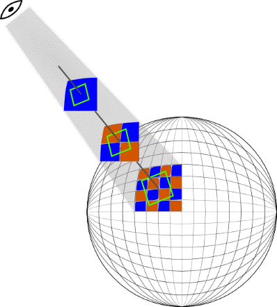
PNG image files created by the script above are shown on Picture 7.
Picture 7 - Representation of the rhomb shape by geographical tiles
To proceed routine of creating one tile we just call method DrawPartObjectShapeOnTile() of ShapeToTileRendering class:
public void DrawPartObjectShapeOnTile(SqlGeometry shape, int X, int Y, int Zoom, string argbFill,
string argbStroke, int strokeWidth)
{
PasteShapeOnTile(CreateColor(argbFill), CreateColor(argbStroke), strokeWidth,
CutPolygonByZoomedPixelZeroTile(shape, X, Y, Zoom));
}
In the method PasteShapeOnTile() was implemented a drawing of a gotten as a parameter list of geometry on a bitmap.
private void PasteShapeOnTile(Color fillcolor, Color strokecolor, int width, List<SqlGeometry> geom)
{
SqlGeometry shape = geom[0];
int geomnum = (int) shape.STNumGeometries();
SqlGeometry stroke = null;
SqlGeometry ring;
int intnum;
if (geom != null)
switch (GetOpenGisGeometryType(shape))
{
case OpenGisGeometryType.LineString:
case OpenGisGeometryType.MultiLineString:
DrawMultiLineStringBordered2(shape, fillcolor, strokecolor, width, 1);
break;
case OpenGisGeometryType.Polygon:
intnum = (int) shape.STNumInteriorRing();
ring = shape.STExteriorRing();
FillPolygonOnTile(fillcolor, ring.ToPointsArray());
if (geomnum >= 1) stroke = geom[1];
for (int i = 1; i <= intnum; i++)
{
FillTransparentPolygonOnTile(shape.STInteriorRingN(i).ToPointsArray());
}
if (geom.Count > 1)
{
stroke = geom[1];
DrawContourOnTile(stroke, strokecolor, width);
}
break;
case OpenGisGeometryType.MultiPolygon:
break;
}
}
Step 3-7, acquiring a filling area and contour lines for specified tile, are implemented in the method CutPolygonByZoomedPixelZeroTile().
private List<SqlGeometry> CutPolygonByZoomedPixelZeroTile(SqlGeometry poly, int X, int Y, int Z)
{
return CutZoomedPixelPolygonByZeroTile(_parser.ConvertToZoomedPixelZeroedByTileGeometry(poly,Z,X,Y);
}
In a class GeometryParser was implemented methods to convert of geometry degree coordinates to pixels and all pixel coordinates are substracted by top left pixel numbers of a target tile, so we obtain coordinates on a zero tile:
public SqlGeometry ConvertToZoomedPixelZeroedByTileGeometry(SqlGeometry shape,int zoom,
int tileX,int tileY)
{
return CreateGeometryFromZoomedPixelInfo
(ConvertToGeometryZoomedPixelsZeroTileShiftedInfo(
GetGeometryInfo(shape), zoom, tileX, tileY));
}
private GeometryZoomedPixelsInfo ConvertToGeometryZoomedPixelsZeroTileShiftedInfo
(GeometryInstanceInfo info, int zoom, int x, int y)
{
int tilezeroshiftX = x*TILE_SIZE;
int tilezeroshiftY = y*TILE_SIZE;
var result = new GeometryZoomedPixelsInfo();
var pixelCoordsListList = new List<List<GeometryPixelCoords>>();
var geomPixCoordsList = new List<GeometryPixelCoords>();
var coords = new GeometryPixelCoords {InnerRing = false};
OpenGisGeometryType type = info.ShapeType;
result.ShapeType = type;
switch (type)
{
case OpenGisGeometryType.Point:
PointF[] geopoints = info.Points[0][0].PointList;
coords.PixelCoordList = new[]
{new Point{X = _conv.FromLongitudeToXPixel(geopoints[0].X, zoom) - tilezeroshiftX,
Y = _conv.FromLatitudeToYPixel(geopoints[0].Y, zoom) - tilezeroshiftY }
};
geomPixCoordsList.Add(coords);
pixelCoordsListList.Add(geomPixCoordsList);
break;
case OpenGisGeometryType.LineString:
coords.PixelCoordList =
GetPixelCoordsShifted(
info.Points[0][0].PointList,
zoom,
tilezeroshiftX,
tilezeroshiftY);
geomPixCoordsList.Add(coords);
pixelCoordsListList.Add(geomPixCoordsList);
break;
case OpenGisGeometryType.Polygon:
foreach (var list in info.Points)
foreach (GeometryPointSequence pointseq in list)
{
coords.PixelCoordList =
GetPixelCoordsShifted(pointseq.PointList, zoom, tilezeroshiftX, tilezeroshiftY);
coords.InnerRing = pointseq.InnerRing;
geomPixCoordsList.Add(coords);
}
pixelCoordsListList.Add(geomPixCoordsList);
break;
case OpenGisGeometryType.MultiPoint:
case OpenGisGeometryType.MultiLineString:
case OpenGisGeometryType.MultiPolygon:
pixelCoordsListList =
GetGeometryPixelCoordsShifted(info.Points, zoom, tilezeroshiftX, tilezeroshiftY);
break;
case OpenGisGeometryType.GeometryCollection:
GeometryInstanceInfo[] geomColl = info.GeometryInstanceInfoCollection;
int n = info.GeometryInstanceInfoCollection.Length;
var geomPixZoomInfoCollection = new GeometryZoomedPixelsInfo[n];
for (int i = 0; i < n; i++)
{
var geom = new GeometryZoomedPixelsInfo();
geom.ShapeType = geomColl[i].ShapeType;
geom.Points =
GetGeometryPixelCoordsShifted(geomColl[i].Points, zoom, tilezeroshiftX, tilezeroshiftY);
geomPixZoomInfoCollection[i] = geom;
}
result.GeometryInstanceInfoCollection = geomPixZoomInfoCollection;
break;
}
if (type != OpenGisGeometryType.GeometryCollection) result.Points = pixelCoordsListList;
return result;
}
In the ShapeToTileRendering class implemented method CutZoomedPixelPolygonByZeroTile()
In the method we do cutting of geometry by the frame of a tile. Lets mention what coordinates in poly are pixel positions relative to top left pixel of the target tile, Here we have listing of method:
private List<SqlGeometry> CutZoomedPixelPolygonByZeroTile(SqlGeometry poly, int X, int Y)
{
List<SqlGeometry> result = new List<SqlGeometry>();
SqlGeometry stroke = null;
SqlGeometry contour;
SqlGeometry tileLineString;
SqlGeometry tobecut;
SqlGeometry tile = _conv.GetTilePixelBound(0, 0, 1);
var tiled = poly.STIntersection(tile);
result.Add(tiled);
switch (GetOpenGisGeometryType(tiled))
{
case OpenGisGeometryType.Polygon:
contour = PolygonToMultiLineString(tiled);
tileLineString = tile.ToLineString();
tobecut = contour.STIntersection(tileLineString);
stroke = contour.STDifference(tobecut);
break;
case OpenGisGeometryType.MultiPolygon:
contour = MultiPolygonToMultiLineString(tiled);
tileLineString = tile.ToLineString();
tobecut = contour.STIntersection(tileLineString);
stroke = contour.STDifference(tobecut);
break;
}
result.Add(stroke);
return result;
}
So we would like to automate the whole process of tiles rendering for objects from the table.
Procedure tile.FillShapeTiles fills list of tiles to be rendered by the geometry in parameter @GeoData and then saves created tile images to file system by specified path in parameter @FolderPath.
In procedure we use following CLR functions imported in database:
tile.ShapeTile(),
tile.SaveToFolderByZoomXY().
Functions implemented in class BitmapFunctions of SQL CLR assembly SqlBitmapOperation.
ShapeTile() returns an image in PNG format with part of the object shape drawn on current tile:
[SqlFunction]
public static SqlBinary
ShapeTile(SqlGeometry shape, SqlInt32 zoom,  SqlInt32 xTile, SqlInt32 yTile,
          SqlString argbFill,SqlString argbStroke,SqlInt32 strokeWidth)
{
  SqlBinary result = null;
  using (ShapeToTileRendering paster = new ShapeToTileRendering())
  {
    using (MemoryStream ms = new MemoryStream())
    {
      try
      {
        paster.DrawPartObjectShapeOnTile
          (shape,
           (int) xTile,
           (int) yTile,
           (int) zoom,
           argbFill.ToString(),
           rgbStroke.ToString(),
           (int) strokeWidth);
        result = paster.GetBytes();
      }
      catch (System.Exception ex)
      {
        string innerMessage = ex.InnerException.Message;
        throw
          new Exception(
            string.Format("zoom: {1}; X:{2}; Y:{3} {0} , inner: {4}",
                          shape, zoom, xTile,yTile, innerMessage));
      }
      return result;
    }
  }
}
SQL CLR assembly SqlBitmapOperation utilizes methods implemented in TileRendering library.
TileRendering library uses following .NET assemblies:
- System
- Microsoft.SqlServer.Types
- System.Drawing
Detailed information how to load assembly into database here Deploying CLR Database Objects
After compiling of SqlBitmapOperation and TileRendering libraries, they are to be imported to the database from file system. As a prerequisite it is necessary to import used by them assemblies. To load assemblies by following script, they should exist in a specified folder:
CREATE ASSEMBLY [Microsoft.SqlServer.Types]
AUTHORIZATION [dbo]
FROM 'd:\SQLCLR\BIN\TileRendering\Microsoft.SqlServer.Types.dll'
WITH PERMISSION_SET = UNSAFE
GO
CREATE ASSEMBLY [System.Drawing]
AUTHORIZATION [dbo]
FROM 'd:\SQLCLR\BIN\TileRendering\ System.Drawing.dll'
WITH PERMISSION_SET = UNSAFE
GO
CREATE ASSEMBLY [TileRendering]
AUTHORIZATION [dbo]
FROM 'd:\SQLCLR\BIN\TileRendering\TileRendering.dll'
WITH PERMISSION_SET = UNSAFE
GO
CREATE ASSEMBLY nQuant.Core
FROM 'd:\SQLCLR\BIN\TileRendering\ nQuant.Core.dll'
WITH PERMISSION_SET = UNSAFE
GO
CREATE ASSEMBLY SqlBitmapOperation
FROM 'd:\SQLCLR\BIN\TileRendering\SqlBitmapOperation.dll'
WITH PERMISSION_SET = UNSAFE
GO
SqlBitmapOperation uses nQuant.Core library from https://nquant.codeplex.com/ for research purpose. This library allows to create image in 8 bit per pixel format with using palette.
As far as SqlGeometry type and other methods from Microsoft.SqlServer.Types are used in our methods it is in need to be imported to the database too.
System.Drawing – it is an wrapper of GDI+ library with an unmanaged code inside.
https://msdn.microsoft.com/en-us/library/ms345106.aspx
TileRendering and SqlBitmapOperation have access to resources outside the database server, so it is necessary to import them with security level EXTERNAL_ACCESS. With this security level it requires to create asymmetric key for an assembly or set to ON TRUSTWORTHY database property, with the following script:
ALTER DATABASE [dataBaseName] SET TRUSTWORTHY ON;
See more information about security by follwing link:
CLR Integration Security
To use functions in stored procedures, after CLR assemblies are imported in database it is time to declare CLR functions from assembly:
CREATE AGGREGATE [tile].[TileAgg]
(@Value [varbinary](max))
RETURNS[varbinary](max)
EXTERNAL NAME [SqlBitmapOperation].[TileAgg]
GO
CREATE AGGREGATE [tile].[IconTileAgg]
(@Value [varbinary](max), @PixelX [int], @PixelY [int])
RETURNS[varbinary](max)
EXTERNAL NAME [SqlBitmapOperation].[IconTileAgg]
GO
CREATE FUNCTION [tile].[IconTile]
(@image [varbinary](max), @zoom [int], @Lon [float], @Lat [float], @xTile [int], @yTile [int], @scale [float])
RETURNS [varbinary](max) WITH EXECUTE AS CALLER
AS
EXTERNAL NAME [SqlBitmapOperation].[BitmapFunctions].[IconTile]
GO
CREATE FUNCTION [tile].[ShapeTile](@shape GEOMETRY, @zoom [int], @xTile [int], @yTile [int], @argbFill NVARCHAR(10),@argbStroke NVARCHAR(10), @strokeWidth INT)
RETURNS [varbinary](max) WITH EXECUTE AS CALLER
AS
EXTERNAL NAME [SqlBitmapOperation].[BitmapFunctions].[ShapeTile]
GO
CREATE FUNCTION tile.SaveToFolderByZoomXY(@image VARBINARY(MAX),@rootFolderPat NVARCHAR(512) , @Zoom [int], @xTile [int], @yTile [int])
RETURNS BIT WITH EXECUTE AS CALLER
AS
EXTERNAL NAME [SqlBitmapOperation].[BitmapFunctions].[SaveToFolderByZoomXY]
GO
The purpose of class ShapeToTileRendering is to draw object geometry on a tile. As we discussed earlier a conversion from spherical coordinates of projection 4326 to pixels of specified zoom level take precedence of a drawing. Conversions implemented in GeometryParser class. After conversion we have geometry in the projection PSG3857. Method PastShapeOnTile just put geometry passed in parameter geom on the tile image. As we remember size of an image tile in our case is always 256 pixels on all zoom levels.
void PasteShapeOnTile(Color fillcolor,Color strokecolor, int width, List<SqlGeometry> geom)
{
SqlGeometry shape = geom[0];
int geomnum = (int)shape.STNumGeometries();
SqlGeometry stroke = null;
SqlGeometry ring;
int intnum;
if (geom != null)
switch (GetOpenGisGeometryType(shape))
{
case OpenGisGeometryType.LineString:
case OpenGisGeometryType.MultiLineString:
DrawMultiLineStringBordered2(shape, fillcolor, strokecolor, width, 1);
break;
case OpenGisGeometryType.Polygon:
intnum = (int)shape.STNumInteriorRing();
ring = shape.STExteriorRing();
FillPolygonOnTile(fillcolor, ring.ToPointsArray());
if (geomnum >= 1) stroke = geom[1];
for (int i = 1; i <= intnum; i++)
{
FillTransparentPolygonOnTile(shape.STInteriorRingN(i).ToPointsArray());
}
if (geom.Count > 1)
{
stroke = geom[1];
DrawContourOnTile(stroke, strokecolor, width);
}
break;
case OpenGisGeometryType.MultiPolygon: break;
}
}
Stored procedure tile.FillShapeTiles can be used only for one object, here is listing of this:
CREATE PROC tile.FillShapeTiles
            @GeoData GEOMETRY, @fillArgb VARCHAR(20),@strokeArgb VARCHAR(20),
            @FolderPath NVARCHAR(20),
            @EndZoom INT = 17, @StartZoom INT = 4, @Thickness INT = 2
AS BEGIN
  IF @EndZoom < @StartZoom OR @GeoData IS NULL RETURN
  INSERT INTO tile.tile (Zoom, X,Y,Data)
  SELECT t.Zoom,
         t.TileX AS X,
         t.TileY AS Y,
         tile.ShapeTile(@GeoData, t.Zoom, t.TileX, t.TileY, @fillArgb, @strokeArgb ,@Thickness) AS Data   FROM
   (SELECT * FROM tile.fn_FetchGeometryTilesZoomDepth(@GeoData,@StartZoom, @EndZoom - @StartZoom))
  SELECT tile.SaveToFolderByZoomXY(Data, @FolderPath, Zoom, X, Y)
  FROM tile.Tile
END
In case of large amount of objects, more than 100 000 for example, on each tile possibly will be drawn geometries of a few objects. It will bring necessity to combine tiles with different objects into single one. To achieve this let’s just use CLR aggregate.
In procedure tile.FillShapeTilesIntersection() we use our CLR function tile.ShapeTile() to create tile image in PNG format by a gotten geometry , tile position numbers and style to draw. Our CLR aggregate tile.TileAgg(@Data VARBINARY(MAX)) combines tiles with the same position in a single tile. As parameters it accepts binary sequence of bytes of tile image in PNG format. To combine tiles by this aggregate we need to group rows by tile position numbers, which are: Z, X, Y.
In each CLR aggregate to be implemented following methods:
- Init();
- Accumulate(value);
- Merge(Agg);
- Terminate()
using System;
using System.Collections.Generic;
using System.Data.SqlClient;
using System.Data.SqlTypes;
using Microsoft.SqlServer.Server;
using TileRendering;
using System.IO;
using System.Drawing;
using System.Drawing.Imaging;
[Serializable]
[SqlUserDefinedAggregate(Format.UserDefined, IsInvariantToDuplicates = true, IsInvariantToNulls = true, IsInvariantToOrder = false, IsNullIfEmpty = false, MaxByteSize = -1)]
public struct TileAgg : IBinarySerialize
{
Bitmap _bitmap;
ImageFormat _format;
Graphics _graphics;
ImageCodecInfo _codecInfo;
const int TILE_SIZE = 256;
Bitmap GetInitialTile()
{
Bitmap DrawArea = new Bitmap(TILE_SIZE, TILE_SIZE);
using (Graphics xGraph = Graphics.FromImage(DrawArea))
{
xGraph.FillRectangle(Brushes.Transparent, 0, 0, TILE_SIZE, TILE_SIZE);
_graphics = Graphics.FromImage(DrawArea);
return DrawArea;
}
}
#region [Aggregate artifacts]
public void Init()
{
_codecInfo = GetEncoderInfo("image/png");
_bitmap = GetInitialTile();
DetectFormat();
}
public void Accumulate(SqlBinary Value)
{
using (MemoryStream ms = new MemoryStream())
{
ms.Write(Value.Value, 0, Value.Length);
ms.Seek(0, SeekOrigin.Begin);
ms.Position = 0;
PasteFromStreamImageToTile( ms);
}
}
public void Merge(TileAgg Group)
{
PasteGroup(Group.Terminate());
}
public SqlBinary Terminate()
{
return GetBytes();
}
#endregion [Aggregate artifacts]
void PasteFromStreamImageToTile( Stream stream)
{
using (Bitmap iconImage = new Bitmap(stream, false))
{
DetectFormat();
int width = iconImage.Width;
int height = iconImage.Height;
var area = new Rectangle(0, 0, width, height);
CopyRegionIntoImage(iconImage,area, area);
}
}
void CopyRegionIntoImage(Bitmap srcBitmap, Rectangle srcRegion, Rectangle destRegion)
{
_graphics.DrawImage(srcBitmap, destRegion, srcRegion, GraphicsUnit.Pixel);
srcBitmap.Dispose();
}
void PasteGroup(SqlBinary Value)
{
using (MemoryStream ms = new MemoryStream())
{
ms.Write(Value.Value, 0, Value.Length);
ms.Seek(0, SeekOrigin.Begin);
ms.Position = 0;
PasteTile(ms);
}
}
void PasteTile(Stream stream)
{
Rectangle bounds = new Rectangle(0, 0, TILE_SIZE, TILE_SIZE);
CopyRegionIntoImage(new Bitmap(stream), bounds, bounds);
}
byte[] GetBytes()
{
return _bitmap.ToByteArray(ImageFormat.Png);
}
#region [IBinarySerialize]
public void Read(BinaryReader reader)
{
_bitmap = new Bitmap(new MemoryStream(reader.ReadBytes((int)reader.BaseStream.Length)));
DetectFormat();
}
public void Write(BinaryWriter writer)
{
EncoderParameters encodeParams = new EncoderParameters(1);
encodeParams.Param[0] = new EncoderParameter(System.Drawing.Imaging.Encoder.Quality, 100);
_bitmap.Save(writer.BaseStream, _codecInfo, encodeParams);
}
#endregion [IBinarySerialize]
void DetectFormat()
{
_format = _bitmap.GetImageFormat();
}
ImageCodecInfo GetEncoderInfo(string mimeType)
{
string lookupKey = mimeType.ToLower();
ImageCodecInfo foundCodec = null;
Dictionary<string, ImageCodecInfo> encoders = Encoders();
if (encoders.ContainsKey(lookupKey))
{
foundCodec = encoders[lookupKey];
}
return foundCodec;
}
private Dictionary<string, ImageCodecInfo> Encoders()
{
Dictionary<string, ImageCodecInfo> encoders = new Dictionary<string, ImageCodecInfo>();
foreach (ImageCodecInfo codec in ImageCodecInfo.GetImageEncoders())
{
encoders.Add(codec.MimeType.ToLower(), codec);
}
return encoders;
}
}
In our scenario in stored procedure as source data table tile.Shape is used. In stored procedure tile.FillShapeTilesIntersection, parameter @StartZoom – is a zoom level number from which we start filling, @EndZoom - is an end zoom level number, till which filling is proceeded. In fields tile.Shapes.fillArgb and tile.Shapes.strokeArgb a color of painting and a contour colour are stored respectively. Here is used folllowing format: AARRGGBB, where AA – alpha channel (transparency), RR – red component, GG - green component, BB – blue component in a hexadecimal representation. For example: DDDDFFDD.
CREATE PROC tile.FillShapeTilesIntersection( @StartZoom INT, @EndZoom INT)
AS
BEGIN
DECLARE @Shape GEOMETRY
DECLARE @CurrentZoom INT
DECLARE @ObjectTypeID INT
DECLARE @fillArgb NVARCHAR(10), @strokeArgb NVARCHAR(10)
IF @ObjectTypeID IS NOT NULL
BEGIN
  SET @CurrentZoom = @StartZoom
  DECLARE shape_cursor CURSOR FOR
  SELECT o.Shape, fillARGB, strokeARGB
  FROM tile.Shape o
  OPEN shape_cursor
  FETCH NEXT FROM shape_cursor INTO @Shape, @fillArgb, @strokeArgb                                        WHILE @@FETCH_STATUS = 0
  BEGIN
    SET @CurrentZoom = @StartZoom
    WHILE @CurrentZoom  <= @EndZoom
    BEGIN
      INSERT INTO tile.tileOverlap (Zoom, X,Y,Data)
      SELECT t.Zoom, t.TileX AS X,t.TileY AS Y,
             tile.ShapeTile(@Shape, t.Zoom, t.TileX, t.TileY, @fillArgb, @strokeArgb ,2) AS Data
      FROM (SELECT * FROM  tile.fn_FetchGeometryTiles(@Shape,@CurrentZoom)) t                                 SET @CurrentZoom = @CurrentZoom + 1
    END
    FETCH NEXT FROM shape_cursor INTO @Shape, @fillArgb, @strokeArgb
  END
  CLOSE shape_cursor;
  DEALLOCATE shape_cursor;
  DELETE tile.TileOverlap
  END
END
Once stored procedure tile.FillShapeTilesIntersection is called, in the table tile.tileOverlap we have images of the tiles with non unique position numbers. Now we are going to combine them by our CLR Aggregate tile.TileAgg:
INSERT INTO tile.Tile (Zoom, X, Y, Data)
SELECT Zoom, X, Y, tile.TileAgg(Data)
FROM tile.tileOverlap
GROUP BY Z, X, Y
Conclusion
Nevertheless this library is just a prototype, if you are still here, you know how to create you own tile rendering system. Possibly it may be a weird thing to create tile images inside SQL Server database and may be is not very reasonable, some body says. Any way it was passed through and shared here.
Sorce code of the library on github
This member has not yet provided a Biography. Assume it's interesting and varied, and probably something to do with programming.


 General
  News
News  Suggestion
  Question
  Bug
Bug  Answer
  Joke
Joke  Praise
  Rant
Rant  Admin
Admin 


